C.I.B. UNIGAS - M03957CI
29
shaft the air damper closes and the air flow rate decreases.
Note:
once the procedure is perfomed, be sure that the blocking nut
RA
is fasten. Do not change the position of the air damper
rods.
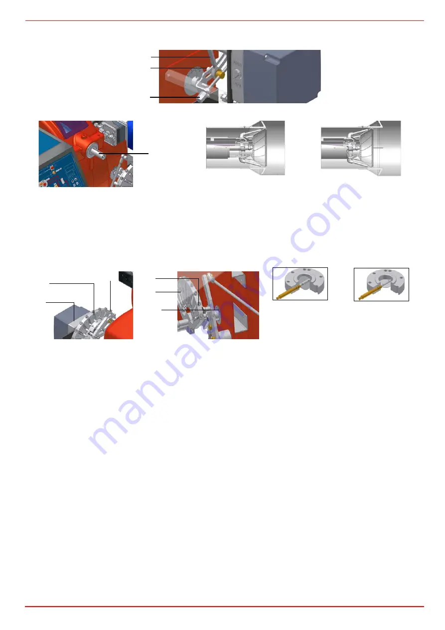
11 The burner is factory-set with the head in its MAX position (maximum output). To let the burner operate at a lower output, turn
clockwise the
VRT
screw and move progressively the combustion head back towards the MIN position.
12
Attention!
if it is necessary to change the head position, repeat the air and gas adjustments described above.The air and gas rate
are now adjusted at the maximum power stage, go on with the point to point adjustement on the
SV1
(gas side) adjusting cam as
to reach the minimum output point.
13 as for the point-to-point regulation, move the gas low flame microswitch (cam III) a little lower than the maximum position (90°);
14 set the
TAB
thermostat to the minimum (as far as Fully-modulating burners, see next paragraphs) in order that the actuator moves
progressively towards the low flame position;
15 move cam III to the minimum to move the actuator towards the low flame until the two bearings find the adjusting screw that refers
to the lower position: screw
V1
to increase the rate, unscrew to decrease.
16 Move again cam III towards the minimum to meet the next screw on the adjusting cam and repeat the previous step; go on this way
as to reach the desired low flame point.
Now adjust the pressure switches (see next par.).
VRA
RA
TR
“MAX” head position
“MIN” head position
VRT
SC
SV1
V1
ID1
V1
SV1
Gas throttle valve open
Gas throttle valve closed
Summary of Contents for HP60
Page 9: ...C I B UNIGAS M03957CI 9 Overall dimensions mm Boiler recommended drilling template ...
Page 49: ...C I B UNIGAS M03957CI 49 ...
Page 51: ...C I B UNIGAS M03957CI 51 WIRING DIAGRAM Cod 05 680 Progressive burners ...
Page 52: ...C I B UNIGAS M03957CI 52 WIRING DIAGRAM Cod 05 681 Fully modulating burners ...
Page 54: ......
Page 55: ......
Page 56: ......


