PART I: SPECIFICATIONS
14
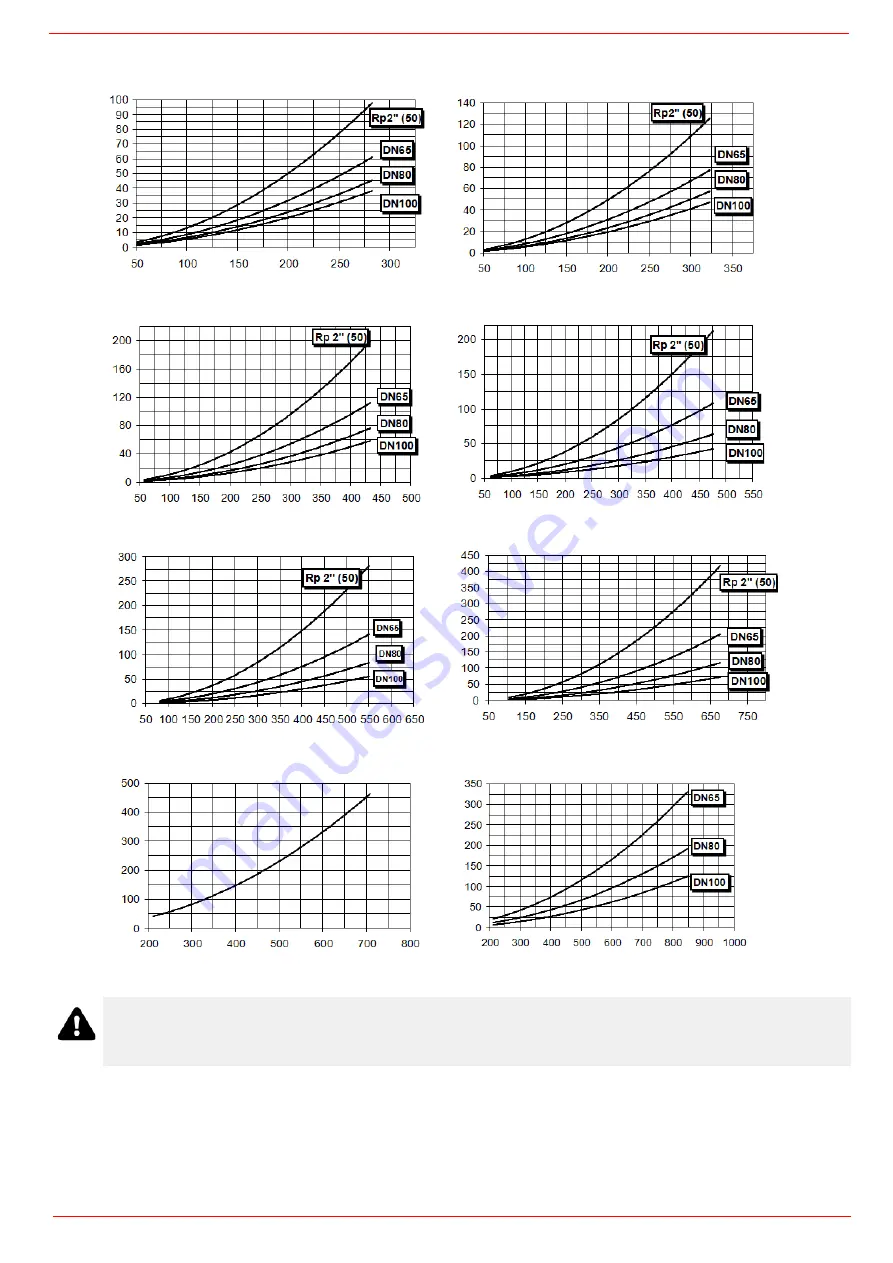
Pressure in the Network / gas flow rate curves (natural gas)
GAS P
R
ES
SURE
mbar
HR91A MG..
Stm
3
/h
HR92A MG..
Stm
3
/h
GAS PRESSURE
mbar
HR93A MG..
Stm
3
/h
HR512A MG..
Stm
3
/h
GAS PRESSURE
mbar
HR515A MG..
Stm
3
/h
HR520A MG..
Stm
3
/h
GAS PRESSURE m
b
ar
HR525A MG.. Rp2
Stm
3
/h
HR525A MG.. DN65-80-100
Stm
3
/h
ATTENTION: the gas rate value is quoted on the x-axis, the related network pressure is quoted on the y-axis
(pressure value in the combustion chamber is not included). To know the minimum pressure at the gas train inlet,
necessary to get the requested gas rate, add the pressure value in the combustion chamber to the value read on
the y-axis.
Summary of Contents for HR92A
Page 45: ...PART III OPERATION 45 Fig 8...
Page 46: ...PART III OPERATION 46...
Page 57: ...Service manual AZL2x LMV2x 3x Burner Management System M12916CD Rev 3 4 03 2023...
Page 64: ...8 Parameters level heating engineer...
Page 106: ...50 ERROR CODE TABLE...
Page 107: ...51...
Page 108: ...52...
Page 109: ...53...
Page 110: ...54...
Page 111: ...55...
Page 112: ...56...
Page 113: ...57...
Page 114: ...58...
Page 115: ...59...
Page 116: ...60...
Page 117: ...61...
Page 118: ...62...
Page 119: ...63...
Page 120: ...64...
Page 125: ......
Page 126: ......
Page 127: ......
Page 129: ......
Page 130: ......
Page 131: ......
Page 132: ......
Page 133: ......
Page 134: ......
Page 135: ......
Page 136: ......
Page 137: ......
Page 138: ......
Page 139: ......
Page 140: ......


