6
Motor connection variants for INVERTER size D
X1 terminal no.
Designation
Assignment
1
L1
Mains phase 1
2
L2
Mains phase 2
3
L3
Mains phase 3
4
PE
Protective conductor
Tab. 1 - X1 terminal assignment - 3 x 400 VAC
X4 terminal no.
Designation
Assignment
1
PE
Protective conductor
2
U
Mains phase 1
3
V
Mains phase 2
4
W
Mains phase 3
Tab. 2 - X1 terminal assignment - 3 x 400 VAC
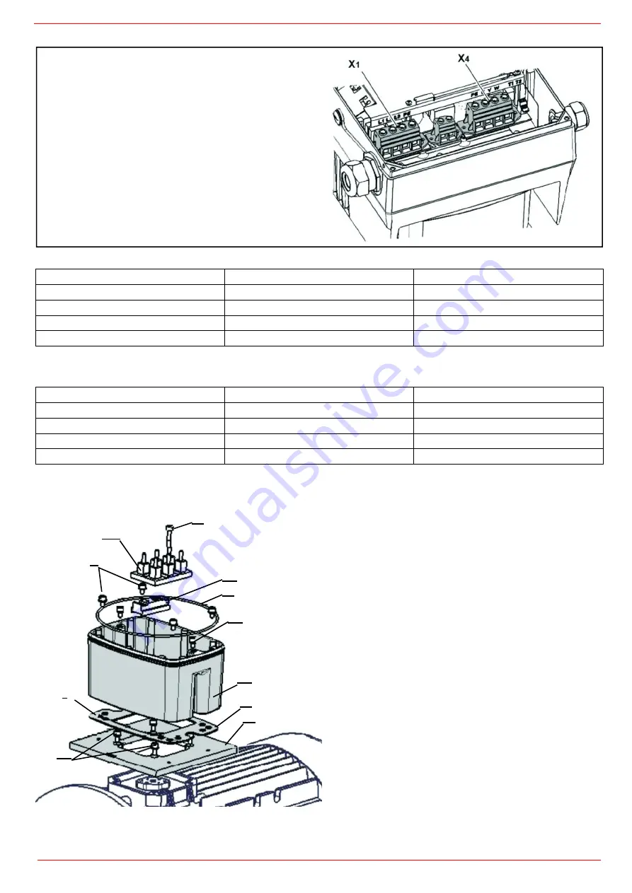
Fig. 2 – Assembly sequence: Connection box – adapter plate size D
Key:
1 Adapter plate option (variant)
2 Holes depending on motor
3 Seal
4 Retaining bolts with spring elements
5 O-ring seal
6 INVEOR / adapter plate support
7 Terminal heightening option
8 Original terminal (not included)
9 Extended screw option (for pos.7)
10 Retaining bolts with spring elements option
11 INVEOR/support retaining bolts
9
8
4
7
5
11
6
2
3
1
10
Summary of Contents for HTLX92R
Page 57: ...Siemens LMV5x Service Manual M12920CC rev 2 1 08 2017...
Page 64: ...8...
Page 68: ...12 2 2 LMV5x program structure...
Page 95: ...39...
Page 102: ......
Page 103: ......
Page 104: ...Note Specifications and data subject to change Errors and omissions excepted...
Page 106: ...Annex1 Example for motor cable...
Page 107: ......
Page 108: ...Annex 2 Example for sensor cable...
Page 109: ......
Page 110: ......
Page 114: ......


