PART II: INSTALLATION
17
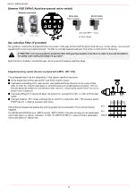
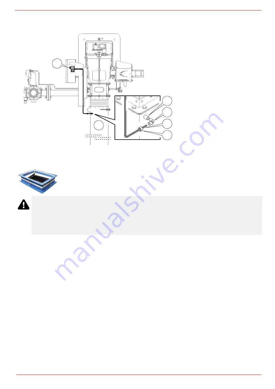
Connection diagram of the air pressure switch to the burner air conduct
Fan installation
ATTENTION! The bellows unit provided is made of canvas and is provided with blocking spacers to avoid
breaking it during installation: first place the bellows unit between flanges, then remove the spacers. Canvas has
to be stretched after the installation, but not stressed.
ATTENTION! the air duct dimensioning must be perforformed according to the flow rate, the temperature, the
distance between the fan and the burner and according to the fan features as well..
ATTENTION! It is suggested to install the fan on vibration-damping supports in order to reduce vibration
propagation.
A
B
C
D
E
P1
Iron sleeve Ø 10 mm
Male elbow fitting Ø 6 mm x 10
Copper tube Ø 6 mm x 1,5 mt
Nut for male elbow fitting Ø 6 mm x 10 mm
Burner air pressure switch
Air conduct
Copper tube connection Ø 6 mm:
- Drill the air duct (with hole from Ø 10 mm);
- Fit sleeve
A
(Ø 10 mm) and weld it on channel
E
;
- Assemble in sequence the
B-D
details on the tube (Ø 6 mm)
C
appropriately shaped up to the connection on the air
pressure switch (
P1
).
Picture refers to application with air pressure switch
mounted on the junction box. Other applications are
provided with air pressure switch mounted on the air
damper.
Connect the air duct to the burner by means of the bellows unit provided together with the burner (see the
picture below).Install the bellows units provided as explained on pages 13-14.
Summary of Contents for HTLX92R
Page 57: ...Siemens LMV5x Service Manual M12920CC rev 2 1 08 2017...
Page 64: ...8...
Page 68: ...12 2 2 LMV5x program structure...
Page 95: ...39...
Page 102: ......
Page 103: ......
Page 104: ...Note Specifications and data subject to change Errors and omissions excepted...
Page 106: ...Annex1 Example for motor cable...
Page 107: ......
Page 108: ...Annex 2 Example for sensor cable...
Page 109: ......
Page 110: ......
Page 114: ......


