PART II: INSTALLATION
20
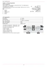
Threaded train with MultiBloc MBE - Mounting
Mounting VD-R & PS-...
1. Gas pressure regulation is possible with VD-R and PS pressure sensor only.
WARNING! For US/CN installation, the output pressure must be monitoried by min. and max. pressure switches set
to +/- 20% of the setpoint.
2. Mounting on pipe. Sensor position: 5x DN according to MBE. Pipe fitting with female thread size ¼, mount sensor with
seal, observe torque.
3. The pressure sensor includes a vent limiter according to UL 353 and ANSI Z21.18/CSA 6.3. No venting required in loca-
tions where vent limiters are accepted by the jurisdiction.
4. Only PS pressure sensors specified by DUNGS are authorised to be connected to the VD-R‘s M12 interface.
5. Only PS cables specified by DUNGS are authorised to be used to connect the PS to the VD-R. Max. cable length 3 m.
A
A
C
B
B
C
1. Mount flange into pipe systems. Use appropriate sealing agent.
2. Insert VB together with supplied O-rings.
Check current position of O-rings.
3. Tighten supplied screws (8xM8x30) in accordance with section 8.
4. Screws (4xM5x25) for VD assembly are supplied.
5. After installation, perform leakage and functional test.
6. Disassembly in reverse order.
1. Insert studs A.
2. Insert seals B.
3. Insert studs C.
4. Tighten studs in accordance with section 8.
Ensure correct position of the seal!
5. Perform leak and functional tests after mounting.
6. Screws (4xM5x20) for VD assembly are supplied.
A
A
VDR
VD-V
VB
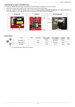
Mounting position MBE / VB / VD
Actuator
VD-R
The actuator
VD-V
does not need any adjustment (funzione ON-OFF)
The actuator
VD-R
It must be combined with the
PS
sensor (include
regolatore di pressione)
Actuator
VD-V
M12 x 5 Pin
VD-R + PS
Summary of Contents for HTLX92R
Page 57: ...Siemens LMV5x Service Manual M12920CC rev 2 1 08 2017...
Page 64: ...8...
Page 68: ...12 2 2 LMV5x program structure...
Page 95: ...39...
Page 102: ......
Page 103: ......
Page 104: ...Note Specifications and data subject to change Errors and omissions excepted...
Page 106: ...Annex1 Example for motor cable...
Page 107: ......
Page 108: ...Annex 2 Example for sensor cable...
Page 109: ......
Page 110: ......
Page 114: ......


