PART III: OPERATION
32
ADJUSTMENTS FOR GAS OPERATION
Adjustments - brief description
The air and fuel rates adjustments must be performed at the maximum ouptput first (“high flame”): see the LMV5.. related manual..
Check that the combustion parameters are in the suggested limits.
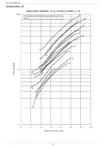
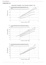
Check the flow rate measuring it on the counter or, if it was not possible, verifying the combustion head pressure by means of a dif-
ferential pressure gauge, as described on par. “Measuring the gas pressure in the combustion head”.
Then, adjust the combustion values by setting the “gas/air” ratio” curvepoints (see the LMV5.. related manual).
Set, now, the low flame output, in order to avoid the low flame output increasing too much or that the flues temperature gets too low
to cause condensation in the chimney.
Adjusting procedure
Go on adjusting the burner.
Users can set only the LMV parameters that can be accessed without password: (see “Adjusting the temperature set-point”).
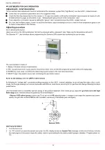
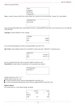
The Siemens AZL User Interface allows programming the Siemens LMV system and monitoring the system data.
The user interface is made of:
1. display: it showes menus and parameters
2. ESC key (previous level): it goes back to the prevoius level menu or exits the programming mode without changing data.
3. ENTER key (next level): it confirms the data changing and jumps to the next menu/parameter.
4. SELECT keys: they select a menu item and change the parameter values.
As far as the settings, see the LMV5 related manual.
By following the “air/gas ratio” curvepoints setting procedure on the LMV5.. manual, adjusting the air and gas flow rates: check, conti-
nuosly, the flue gas analisys, as to avoid combustion with little air; dose the air according to the gas flow rate change following the steps
quoted below.
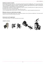
Once the throttle valve is completely opened, acting on the pressure stabiliser of the valves group, adjust the
gas flow rate in the high
flame stage
as to meet the values requested by the boiler/utilisation:
- Siemens VGD valves group:
remove cap
T
and act on the
VR
adjusting screw to increase or decrease the pressure and conse-
quently the gas rate; screwind
VR
the rate increases, unscrewing it decreases (see next figure).
:
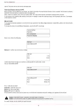
Start-up procedure
1
Turn the burner on.
2
the LMV control box starts the system test cycle: the AZL display shows the
System Test
message; at the end of the test, it shows
the main page and the system stops (the safety chain is open) waiting for the startup enabling signal (standby - Program phase no.
12)
1
2
3
4
VR
T
Siemens VGD..
Summary of Contents for HTLX92R
Page 57: ...Siemens LMV5x Service Manual M12920CC rev 2 1 08 2017...
Page 64: ...8...
Page 68: ...12 2 2 LMV5x program structure...
Page 95: ...39...
Page 102: ......
Page 103: ......
Page 104: ...Note Specifications and data subject to change Errors and omissions excepted...
Page 106: ...Annex1 Example for motor cable...
Page 107: ......
Page 108: ...Annex 2 Example for sensor cable...
Page 109: ......
Page 110: ......
Page 114: ......


