background image

25

MULTIBLOC DUNGS MB-DLE 405..412 
Mounting

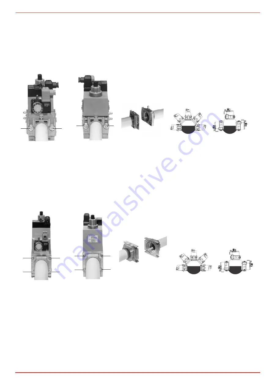
1. Mount flange onto tube lines: use appropriate sealing agent (see Fig. 30);
2. insert MB-DLE: note position of O rings (see Fig. 30);
3. tighten screws A, B, C and D (Fig. 28 - Fig. 29), accordind to the mounting positions (Fig. 31);
4. after installation, perform leakage and functional test;
5. disassembly in reverse order.

MULTIBLOC DUNGS MB-DLE 415..420 

Mounting

1. Loosen screws A and B 

do not 

unscrew (Fig. 28 - Fig. 29).

2. unscrew screws C and D (Fig. 28 - Fig. 29).
3. Remove MultiBloc between the threaded flanges (Fig. 29).
4. After mounting, perform leakage and functional tests.

Once the train is installed, connect the gas valves group plug.

Fig. 24

Fig. 25

Fig. 26

Fig. 27

Fig. 28

Fig. 29

Fig. 30

Fig. 31

A

B

D

C

MOUNTING POSITIONS

A

B

C

D

C

B

D

A

MOUNTING POSITIONS

Summary of Contents for IDEA NG280

Page 1: ...3CA Rel 0 1 09 2010 BURNERS BRUCIATORI BRULERS BRENNER QUEMADORES ГОРЕЛКИ Microprocessor controlled gas burners MANUAL OF INSTALLATION USE MAINTENANCE NG280 NG350 NG400 NGX280 NGX350 NGX400 LG280 LG350 LG400 ...

Page 2: ...ms 27 User interface 29 Setting menu 30 PHASE LIST 31 Entering the Parameter levels 31 Info level 32 Service level 34 SETTING GAS AND AIR FLOW RATE 36 Startup Output 36 Adjustments brief description 36 Adjusting procedure 37 Adjusting the combustion head 38 Fully modulating burners 38 Calibration of air and gas pressure switches 39 Calibration of air pressure switch 39 Calibration of low gas press...

Page 3: ...s electricity gas oil or other fuel Observe caution with hot burner components These are usually near to the flame and the fuel pre heating system they become hot during the unit operation and will remain hot for some time after the burner has stopped When the decision is made to discontinue the use of the burner the user shall have qualified personnel carry out the following operations a Remove t...

Page 4: ...c or explosive mixtures DIRECTIVES AND STANDARDS Gas burners European directives Directive 2009 142 EC Gas Appliances Directive 2006 95 EC on low voltage Directive 2004 108 EC on electromagnetic compatibility Harmonised standards UNI EN 676 Gas Burners CEI EN 60335 1 Household and similar electrical appliances Safety Part 1 General requirements EN 50165 Electrical equipment of non electric applian...

Page 5: ...in the utilisation limits In the double stage progressive and fully modulating burners the electric actuator that moves proportionally the air damper and the gas butterfly valve is controlled by the LMV2 Burner Management System BMS This one allows the optimisation of the gas flue values as to get an efficient combustion The combustion head positioning determines the burner s output Fuel and combu...

Page 6: ...ble gas pressure value upstream the burner s gas valve Then subtract the backpressure The result is called pgas Draw a vertical line matching the furnace input value 600kW in the example quoted on the x axis as far as intercepitng the network pressure curve according to the installed gas train DN65 in the example From the inter ception point draw an horizontal line as far as matching on the y axis...

Page 7: ... Natural gas L P G Category see next paragraph I3B P Gas rate min max Stm3 h 7 32 2 5 11 5 Gas Pressure min max mbar Note2 Power supply 230V 50Hz Total power consumption kW 0 55 Electric motor kW 0 25 Protection IP40 Valves size Gas connection 1 Rp 1 1 Rp 1 1 Rp 1 1 Rp1 1 Rp1 1 1 4 Rp 11 4 Operation Progressive Fully modulating Operating temperature C 10 50 Storage Temperature C 20 60 Working serv...

Page 8: ... 20 60 Working service Intermittent BURNER TYPE LG400 L xx x 25 LG400 L xx x 32 LG400 L xx x 40 LG400 L xx x 50 Output min max kW 105 420 Fuel L P G Category I3B P Gas rate min max Stm3 h 4 16 Gas pressure min max mbar Note2 Power supply 230V 50Hz Total power consumption kW 0 67 0 75 Electric motor kW 0 37 0 45 Protection IP40 Valves size Gas connection 1 Rp 1 1 Rp 1 1 Rp 1 2 Rp 2 Operation Progre...

Page 9: ...ature C 20 60 Working service Intermitent BURNER TYPE NGX350 M xx x 25 NGX350 M xx x 32 NGX350 M xx x 40 Output min max kW 65 260 Fuel Natural gas Category see next paragraph Gas rate min max min max Stm3 h 7 27 5 Gas pressure min max mbar Note2 Power supply 230V 50Hz Total power consumption kW 0 67 Electric motor kW 0 37 Protection IP40 Valves size Gas connection 1 Rp1 1 1 4 Rp 11 4 1 1 2 Rp 11 2...

Page 10: ...0 37 0 45 Protection IP40 Valves size Gas connection 1 Rp 1 1 Rp 1 1 Rp 1 2 Rp 2 Operation Progressive Fully modulating NOx emissions Class 3 EN676 2008 Operating temperature C 10 50 Storage Temperature C 20 60 Working serivce Intermittent Note1 All gas flow rates are referred to Stm3 h 1013 mbar absolute pressure 15 C temperature and are valid for G20 gas net calorific value Hi 34 02 MJ Stm3 for ...

Page 11: ... PRESSURE IN CCOMBUSTION CHAMBER mbar LG280 kW LG350 kW BACK PRESSURE IN CCOMBUSTION CHAMBER mbar LG400 kW 0 1 2 3 4 5 6 7 50 100 150 200 250 300 350 0 2 4 6 50 100 150 200 250 300 350 400 0 1 2 3 4 5 6 7 8 9 100 150 200 250 300 350 400 450 0 1 2 3 4 5 6 7 50 100 150 200 250 300 350 0 2 4 6 50 100 150 200 250 300 350 0 2 4 6 8 50 100 150 200 250 300 350 400 450 ...

Page 12: ...minimum output point is rea ched setting the combustion head to its MIN position During the first ignition the combustion head is set in order to find a compromise between the burner output and the generator specifications that is why the minimum output may be different from the Per formance curve minimum Low NOx burners BACK PRESSURE IN CCOMBUSTION CHAMBER mbar NGX280 kW BACK PRESSURE IN CCOMBUST...

Page 13: ...ustion chamber is not included To know the minimum pressure at the gas train inlet necessary to get the reque sted gas rate add the pressure value in the combustion chamber to the value read on the y axis 0 20 40 60 80 1 00 5 1 0 1 5 20 25 30 35 40 Rp 1 25 Rp 1 32 Rp 20 Rp 1 5 0 20 40 60 80 100 5 10 15 20 25 30 35 40 45 Rp 1 25 Rp 1 40 Rp 1 32 Rp 15 Rp 20 0 2 4 6 8 10 12 14 16 18 10 15 20 25 30 35...

Page 14: ... is not included To know the minimum pressure at the gas train inlet necessary to get the reque sted gas rate add the pressure value in the combustion chamber to the value read on the y axis 0 5 1 0 1 5 20 25 30 4 6 8 1 0 1 2 1 4 1 6 1 8 20 22 24 26 Rp 1 3 2 Rp 1 4 0 Rp 1 2 5 Rp 2 0 0 10 20 30 40 50 60 70 80 5 10 15 20 25 30 35 R p 1 25 R p 1 4 0 R p 1 3 2 R p 20 R p 15 0 20 40 60 80 100 5 10 15 2...

Page 15: ...t on the butterfly valve 4 Differential pressure gauge Measuring the gas pressure in the combustion head In order to measure the pressure in the combustion head insert the pressure gauge probes one into the generator s pressure outlet Fig 4 2 to get the pressure in the combustion chamber and the other one into the butterfly valve s pressure outlet of the burner Fig 4 3 On the basis of the measured...

Page 16: ...h L P G Burners Gas backpressure in combustion head LG280 Gas rate Stm3 h Gas backpressure in combustion head LG350 Gas rate Stm3 h LG400 Gas rate Stm3 h 0 2 4 6 8 1 0 1 2 1 4 1 6 6 1 0 1 4 1 8 22 26 30 34 0 2 4 6 8 10 12 5 10 15 20 25 30 35 40 0 1 2 3 4 5 6 7 8 9 10 15 20 25 30 35 40 45 0 2 4 6 8 1 0 1 2 1 4 1 6 1 8 2 3 4 5 6 7 8 9 1 0 1 1 1 2 1 3 0 5 10 15 20 25 2 4 6 8 10 12 14 0 5 10 15 20 4 6...

Page 17: ...280 Gas rate Stm3 h Gas backpressure in combustion head NGX350 Gas rate Stm3 h NGX400 Gas rate Stm3 h 0 2 4 6 8 1 0 1 2 1 4 4 6 8 1 0 1 2 1 4 1 6 1 8 20 0 2 4 6 8 10 12 14 16 18 6 8 10 12 14 16 18 20 22 24 26 28 30 0 1 2 3 4 5 6 7 8 9 10 5 10 15 20 25 30 35 40 ...

Page 18: ...68 113 164 108 215 223 348 M10 219 131 179 155 459 366 93 128 517 491 NG280 M MD Ex 0 50 2 733 878 163 308 570 798 330 468 113 164 108 215 223 348 M10 219 131 179 155 459 366 93 128 567 491 DN A S A L B S B L C D 5mmE 5mm F G H Y K1 K2 L M N OminOmax P Q R S T W X NG350 M PR Ex 0 25 1 748 878 178 308 570 596 200 396125164144215223348M10219 131 179 1554593669389508491 NG350 M PR Ex 0 32 1 1 4 748 8...

Page 19: ...308 570 798 330 468 117 137 108 215 223 348 M10 219 131 179 155 459 366 93 128 517 491 NGX280 M MD Ex 0 50 2 733 878 163 308 570 798 330 468 117 137 108 215 223 348 M10 219 131 179 155 459 366 93 128 567 491 DN A S A L B S B L C D 5mmE 5mm F G H Y K1 K2 L M N OminOmax P Q R S T W X NGX350 M PR Ex 0 25 1 748 878 178 308 570 596 200 396131164144215223348M10219 131 179 1554593669389508491 NGX350 M PR...

Page 20: ...he boiler manufacturer In absence of these consider the fol lowing Cast iron boilers three pass flue boilers with the first pass in the rear part the blast tube must protrude no more than 100 mm into the combustion chamber Pressurised boilers with flame reversal in this case the blast tube must penetrate at least 50 100 mm into combustion chamber in respect to the tube bundle plate The length of t...

Page 21: ...same screws 5 Assemble the whole piece to the burner by caring attention to the indication in picture Fig 13 If you modify the blast tube length you have to modify also the combustion head length by reading the following instructions 1 Remove the screws V1 and V2 as shown in Fig 14 2 Lower the terminal part of the combustion head by moving it with a slight circular movement until the holes will ma...

Page 22: ...VT2 off Fig 17 3 Take the ignition cable CA off of the transformer 4 Disconnect the connector CR from the printed cirduit Fig 18 5 Take off the flange and the combustion head together Fig 20 6 Take the gas pipe TR off and put it in the new position fixing the screws VT1 and VT2 Fig 19 Fig 14 Fig 15 Fig 16 Fig 17 Fig 18 Fig 19 V2 V1 V1 V2 V3 V4 S1 S2 T VT1 VT2 TR G CA CR LOCKED UNLOCKED G G VT2 VT1...

Page 23: ...n head together 9 Rotate the disc D following the instructions below 10 Take off the screw VF 11 Rotate the disc D for 180 and then fit the screw VF Fig 22 12 Reconnect CR and CA 13 Retighten the screws V1 V2 V3 V4 VT1 e VT2 14 Place again the rod T into its own position and fasten it by the plastic hook G Fig 20 Fig 21 Fig 22 Standard position Fig 23 New position F V D VF TR D ...

Page 24: ...rving the mounting direction for each item NOTE the bellow joint the manual cock and the gaskets are not part of the standard supply The procedures of installation fo the gas valves are showed in the next paragraph ATTENTION BEFORE EXECUTING THE CONNECTIONS TO THE GAS PIPE NETWORK BE SURE THAT THE MANUAL CUTOFF VALVES ARE CLOSED READ CAREFULLY THE WARNINGS CHAPTER AT THE BEGINNING OF THIS MANUAL G...

Page 25: ...m leakage and functional test 5 disassembly in reverse order MULTIBLOC DUNGS MB DLE 415 420 Mounting 1 Loosen screws A and B do not unscrew Fig 28 Fig 29 2 unscrew screws C and D Fig 28 Fig 29 3 Remove MultiBloc between the threaded flanges Fig 29 4 After mounting perform leakage and functional tests Once the train is installed connect the gas valves group plug Fig 24 Fig 25 Fig 26 Fig 27 Fig 28 F...

Page 26: ...he electrical connections pay attention to turn the plant s switch to OFF and be sure that the burner s main switch is in 0 position OFF too Read carefully the chapter WARNINGS and the Electrical connections section WARNING if the cable that connects the thermostats and the control box should be longer than 3 meters insert a sectioning relay following the attached electrical wiring diagram The bur...

Page 27: ...E FU3 LINE FUSE IL BURNER LINE SWITCH IM FAN MOTOR LINE SWITCH KM1 FAN MOTOR CONTACTOR LAF BURNER IN HIGH FLAME INDICATOR LIGHT LB INDICATOR LIGHT FOR BURNER LOCK OUT LBF BURNER IN LOW FLAME SIGNALLING LAMP MV FAN MOTOR ST THERMOSTATS O PRESSURE SWITCHES SERIE TAB HIGH LOW FLAME THERMOSTAT PRESSURE SWITCH TS SAFETY THERMOSTAT PRESSURE SWITCH CONN MOTORE FAN MOTOR CONNECTOR CONN LINEA BURNER POWER ...

Page 28: ...AUXILIARY FUSE IL BURNER LINE SWITCH IM FAN MOTOR LINE SWITCH KM1 FAN MOTOR REMOTE CONTACTOR LANDIS RWF40 MODULATION REGULATOR LB BURNER LOCKOUT SIGNALLING LAMP LBF BURNER IN LOW FLAME SIGNALLING LAMP MV FAN MOTOR SD 0 10V VOLTAGE SIGNAL SD 0 4 20mA CURENT SIGNAL SD PRESS PRESSURE PROBE SMA MAN AUTO SELECTOR SMF OPERATION SELECTOR MIN 0 MAX ST PRESSURE SWITCHES OR THERMOSTATS SERIE TS SAFETY THERM...

Page 29: ...y the code message will appear by entering the proper password it is possible to access the Service mode Info and Enter keys Used for Info and Service menues Used as Enter key in the setting modes Used as Reset key in the burner operation mode Used to enter a lower level menu Key Used to decrease a a value Used to enter Info and Serivce during the curve adjustments Key Used to increase a a value U...

Page 30: ...zioni generali General OEM Service Info 200 Controllo bruciatore Burner control OEM Service 400 Curve rapporto Ratio curves OEM Service 500 Controllo rapporto Ratio control OEM Service 600 Servocomandi Actuators OEM Service 700 Storico errori Error history OEM Service Info 900 Dati di processo Process data OEM Service Info P V h min s Lock unlock codes Flame Open valves Fan motor energised Oil pre...

Page 31: ...on transformer ON Ph42 TSA1 primo tempo sicurezza trasformatore accen sione OFF TSA1 1st safety time ignition transformer OFF t42 preignition time OFF Ph44 t44 intervallo 1 t44 interval 1 Ph50 TSA2 secondo tempo sicurezza TSA2 2nd safety time Ph52 t52 intervallo2 t52 interval 2 Ph60 Funzionamento 1 stazionario Operation 1 stationary Ph62 t62 massimo tempo bassa fiamma funzionamento 2 in preparazio...

Page 32: ...ll show InFo Press the enter InFo key 3 then il will show the first code 167 flashing on the right side it will show the data entered By pressing or it is possible to scroll up or down the parameter list 4 If a dot line is shown on the right there is no enough room for complete visualisation press enter again the data will be completely shown for 1 to 3 seconds By pressing enter or and at the same...

Page 33: ... seconds the display will show 9 Once the last parameter is accessed 143 by pressing the End message will flash 10 Press InFo for more than three seconds or for more than three seconds orto return to the normal display Parameter Description 167 Cubic meters of fule resettable 162 Operating hours resettable 163 Device operating hours 164 Burners start ups resettable 166 Total number of start ups 11...

Page 34: ...t press InFo for one second The unit displays an event which does not lead to shutdown The display shows current error code c alternating with diagnostic code d Press InFo to return to the display of phases Example Error code 111 diagnostic code 0 To reset press InFo for a second Record the codes and check the Error List to find the type of faults Service level To enter the Service mode press InFo...

Page 35: ...essing the End message will blink 3 Press InFo for more than three seconds or for more than three seconds orto return to the normal display For further nformation see tha LMV2 related manual Parameter Description 954 Flame intensity 121 output if set automatic operation 922 Actuators position 00 combustibile 01 aria 161 Lock outs number 701 725 Lock outs History see chapter 23 in the LMV2x manual ...

Page 36: ...he combustion by settin the air gas ratio curvepoints see the LMV2x attached manual Set now the low flame output in order to avoid the low flame output increasing too much or that the flues temperature gets too low to cause condensation in the chimney ATTENTION before starting the burner up be sure that the manual cutoff valves are open and check that the pres sure upstream the gas train complies ...

Page 37: ...rate change following the steps quoted below acting on the pressure stabiliser of the valves group adjust the gas flow rate in the high flame stage as to meet the values requested from the boiler utilisation Multibloc MB DLE the valve is adjusted by means of the RP regulator after slackening the locking screw VB by a number of turns By unscrewing the regulator RP the valve opens screwing the valve...

Page 38: ... how much the combustion head moved Fully modulating burners To adjust the fully modulating burners use the CMF switch on the burner control panel see next picture instead of the TAB thermo stat as described on the previous paragraphs about the progressive burners Go on adjusting the burner as described before paying attention to use the CMF switch intead of TAB The CMF position sets the oprating ...

Page 39: ...in installation diagram until the measu red pressure is reduced by 50 Pay attention that the CO value in the flue gas does not increase Check that the burner is operating correctly Screw down the pressure switch adjusting ring nut until the burner lockout Fully open the manual shut off valve Refit the transparent plastic cover on the pressure switch Adjusting the maximum gas pressure switch when p...

Page 40: ... ELECTRICAL LEADS OPENING THE GENERATOR DOOR DISMANTLING OF PART OF THE BURNER NEVER OPEN OR DISMANTLE ANY COMPONENT OF THE MACHINE OPERATE ONLY THE MAIN SWITCH WHICH THROUGH ITS EASY ACCESSIBILITY AND RAPIDITY OF OPERATION ALSO FUNCTIONS AS AN EMERGENCY SWITCH AND ON THE RESET BUTTON IN CASE OF A BURNER SHUT DOWN RESET THE CONTROL BOX BY MEANS OF THE RESET PUSHBUTTON IF A SECOND SHUT DOWN TAKES P...

Page 41: ...he end of pre purging the air damper is driven to ignition position the ignition transfomer is energised signalled by lamp H on the front panel and few seconds later the EV1 and EV2 gas valves are open lamp L and I on the front panel Few seconds later after the gas valve opening then the ignition transformeris de energised lamp H tunrs to off The burner is now operating in low flame later on the t...

Page 42: ...filter in the MULTIBLOC DUNGS MB DLE 405 412 Check the filter at least once a year Change the filter if the pressure difference between pressure connection 1 and 3 Fig 48 Fig 49 is Dp 10 mbar Change the filter if the pressure difference between pressure connection 1 and 3 Fig 48 Fig 49 is twice as high compared to the last check You can change the filter without removing the fitting 1 Interrupt th...

Page 43: ...Fig 51 Fig 52 is twice as high compared to the last check You can change the filter without removing the fitting 1 Interrupt the gas supply closing the on off valve 2 Remove screws 1 6 Fig 53 3 Change filter insert 4 Re insert filter housing screw in screws 1 6 without using any force and fasten 5 Perform leakage and functional test pmax 360 mbar 6 Pay attention that dirt does not fall inside the ...

Page 44: ...ormer Fig 56 4 Disconnect the connector CR Fig 57 CAUTION during the assembling phase before tightening screws V1 V2 V3 V4 mount and tighten screws S1 and S2 To remove the head the operator must pull it towards himself Once the combustione head is removed check that the air and gas holes are not obstructed Fig 57 H Clean the combustion head by a compressed air blow or in case of scale scrape it of...

Page 45: ...leads to start prevention followed by a restart Extraneous light during the prepurge phase leads to immediate lockout If extraneous light occurs during the shutdown phase the system switches to the safety phase One repetition is permitted This means that if the error occurs again the next time the system is shut down the unit initiates lockout Seasonal stop To stop the burner in the seasonal stop ...

Page 46: ...46 BURNER EXPLODED VIEW ...

Page 47: ...IGNITION CABLE 10 GAS PRESSURE 25 5 DETECTION CABLE 11 MOTOR 26 CONNECTOR 12 GAS VALVES GROUP WITH GOVERNOR 27 CONNECTOR 13 FLANGE 28 1 IGNITION TRANSFORMER 14 PLUG 28 2 AIR PRESSURE SWITCH 15 O RING 28 3 BRACKET 16 AIR FLAP 28 4 CONTACTOR 17 COVER FIXING SCREW 28 5 CONTROL BOX 18 AIR INTAKE 29 1 ACTUATOR BRACKET 19 AIR INTAKE 29 2 ACTUATOR 20 BRACKET 29 3 ADJUSTING BUSH 21 BRACKET 30 1 FRONT CONT...

Page 48: ...RE SWITCH 2160077 2160077 2160077 IGNITION TRANSFORMER MOD COFI 2170138 2170138 2170138 IGNITION TRANSFORMER MOD DANFOSS 2170232 2170232 2170232 MOTOR 2180717 2180714 2180712 VALVE GROUP Rp1 2190341 2190341 2190341 VALVE GROUP Rp1 1 4 2190342 2190342 2190342 VALVE GROUP Rp1 1 2 21903L3 21903L3 21903L3 ACTUATOR SIEMENS SQN14 2480096 2480096 2480096 ACTUATOR SIEMENS RWF 2570112 2570112 2570112 COMBU...

Page 49: ...49 ELECTRICAL WIRING DIAGRAMS See the attached wiring diagrams Wiring diagram SE04 755 Progressive burners Wiring diagram SE04 753 Fully modulating burners ...

Page 50: ......

Page 51: ......

Page 52: ...d and data subject to change Errors and omissions excepted C I B UNIGAS S p A Via L Galvani 9 35011 Campodarsego PD ITALY Tel 39 049 9200944 Fax 39 049 9200945 9201269 web site www cibunigas it e mail cibunigas cibunigas it ...

Reviews: