C.I.B. UNIGAS - M039119CE
23
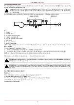
Startup Output
The start-up heat output shall not exceed 120 kW (single stage burners) or 1/3 of nominal output (double-stage, progressive or fully
modulating burners). In order to comply with these requirements, burners are provided with butterfly valve and/or slow-opening safety
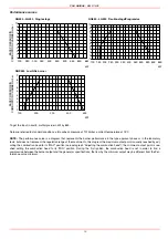
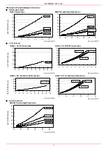
valve. On double-stage, progressive or modulating burners, the low flame ouptut must be higher than the minimum ouptut quoted in the
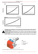
performance curve (see “Gas pressure in combustion head vs. gas flow rate curves” on page 22).
Adjustments - brief description
Adjust the air and gas flow rates at the maximum output (“high flame”) first, by means of the air damper and the adjusting cam respec-
tively.
z
Check that the combustion parameters are in the suggested limits.
z
Check the flow rate measuring it on the counter or, if it was not possible, verifying the combustion head pressure by means of a dif-
ferential pressure gauge, as described on par. “Measuring the gas pressure in the combustion head” on page 20.
z
Then, adjust the combustion values corresponding to the points between maximum and minimum: set the shape of the adjusting
cam foil. The adjusting cam sets the air/gas ratio in those points, regulating the opening-closing of the throttle gas valve.
z
.Set, now, the low flame output, acting on the low flame microswitch of the actuator in order to avoid the low flame output increa-
sing too much or that the flues temperature gets too low to cause condensation in the chimney.
Adjustment procedure
To change the burner setting during the testing in the plant, follows the next procedure, according to the burner operation.
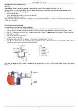
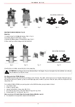
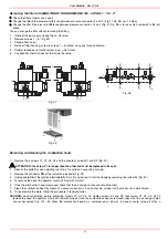
Before starting the burner up, adjust the valves group slow opening: to set the slow opening remove cover
T
, reverse it upside down
and use it as a tool to twist screw
VR
. Decrease the ignition flow rate by screwing, increase it by unscrewing. Do not use a screwdriver
on the screw
VR
!
Note: the screw
VSB
must be removed only in case of replacemente of the coil.
1
remove the burner cover
2
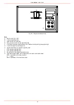
startup the burner by turning its main switch
A
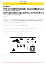
to on: if the burner locks (LED
B
on in the control panel) press the RESET button (
C
)
on the control panel ().
3
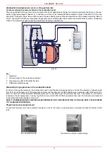
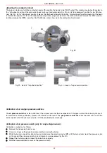
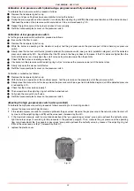
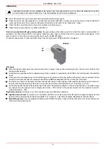
remove the actuator cover: set it to the ignition position (ignition position= 0° on the air damper index
ID
- see figure on pag.23);
4
(Progressive/Fully-modulating burners) Before starting the burner up, drive the high flame actuator microswitch matching the low
flame one (in order to let the burner operates at the lowest output) to safely achieve the high flame stage.
As for the setting, refer to this correspondence table.
z
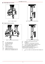
Berger STA12: On this actuator, the manual control of the air damper is not provided; the setting of the cams is carried out working
with a screwdriver on the
VS
screw placed on the cam.
z
Siemens SQN72: a key is provided to move cams I and IV, the other cams can be moved by means of screws. On the Siemens
actuator the AUTO/MAN mode is provided (see picture).
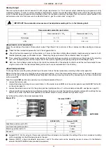
IMPORTANT! the combustion air excess must be adjusted according to the in the following chart.
Recommended combustion parameters
Fuel
Recommended (%) CO
2
Recommended (%) O
2
Natural gas
9 ÷ 10
3 ÷ 4.8
LPG
11 ÷ 12
2.8 ÷ 4.3
Berger STA
Siemens SQN72
BERGER STA
Siemens SQN72
High flame position (set to 90°)
I
I (red)
Low flame and ignition position
IV
III (orange)
Stand-by position (set to 0°)
II
II (blue)
Not used
III
IV (black)
I
II
III
IV
VS
IV
III
II
I
AUTO/MAN


