C.I.B. UNIGAS - M039119CE
24
5
go on adjusting air and gas flow rates: check, continuosly, the flue gas analisys, as to avoid combustion with little air; dose the air
according to the gas flow rate change following the steps quoted below;
6
drive the burner to high flame stage, by means of the thermostat
TAB (except single-stage models)
.
7
acting on the pressure stabiliser of the valves group, adjust the
gas flow rate in the
high flame stage
as to meet the values requested by the boiler/utilisation:
-
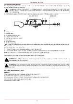
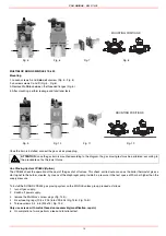
Multibloc MB-DLE:
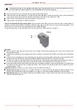
The pressure governor is adjusted by operating the screw
VS
located under the cover
C
. By screwing down the pressure is increased and by
unscrewing it is reduced.
The valve is adjusted by means of the
RP
regulator after
slackening the locking screw
VB
by a number of turns. By unscrewing the regulator
RP
the valve opens, screwing the valve closes. The pressure stabilizer is adjusted by
operating the screw
VS
located under the cover
C
. By screwing down the pressure is
increased and by unscrewing it is reduced.
Pressure stabiliser is factory-set. The setting values must be locally adapted
to machine conditions. Important! Follow the instructions of the burner manufactu-
rer!
To adjust the air flow rate
, proceed as follows, according to the burner operation (single-
stage, double-stage, prograssive or fully-modulating).
z
Adjustements for single-stage burners
8
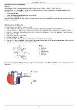
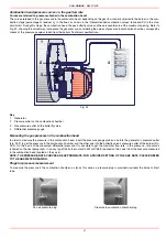
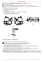
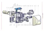
loosen
VR
screw (see picture below)
9
move the
ID
index t or -, in order to increase or decrease the air flow-rate, according to the required combustion values;
10 fasten the
VR
screw again.
z
Double-stage, progressive or fully-modulating burners
11 still in the high flame operation and with the actuator on its 90° position, find the
V
screw on the adjusting cam
SV
(see next pic-
ture), matching with the bearings that move along the foil and related to the actuator position.
12 unscrew the
V
srew to increase the air folw rate, unscrew to decrease it
13 once the maximum flow rate is fixed, shortcircuit for a while, the thermostat
TAB
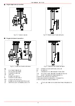
T6 and T7 terminals (see pag. 35), as far as the
fully-modulating burners, see next paragraph. The actuator will move towards the low flame position as to meet the next screw
V
;
then remove the bridge;
14 then adjust the screw
V
related to that position;
15 shortcircuit, again for a while, the
TAB
T6 and T7 terminals and repeat from point 11;
16 repeat all these instructions for all the actuator stroke, in order to define the foil shape.
Note:
If it should be necessary to adjust the rating of the burner in low flame, work on the related actuator cam After this operation,
check the gas rate and verify the combustion values. In case of lack or excess of air, work on the screws
V
of the adjusting cam (see
pictures) matching the setting point of the air rate in low flame; unscrew to increase the air rate or screw to decrease it.
Fully modulating burners
To adjust the air rate in low flame and in the intermediate points, proceed as follow.
1
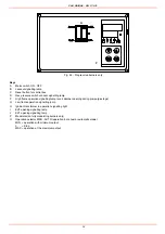
Keep pushed for 5 seconds the EXIT button on the modulator (); when the LED with the hand symbol lights up, press the arrow but-
ton, driving the actuator to the maximum opening position progressively;
2
stop its stroke when it meets each screw
V
: adjust the air rate by adjusting the
V
screw that matches each bearing.
3
Push the EXIT button to quit the manual mode.
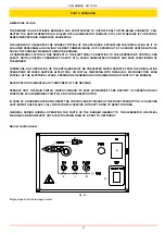
Fig. 26
Fig. 27
C
VS
T(VR)
RP
VB
VSB
VR
ID
V
SC
SV

