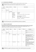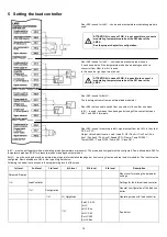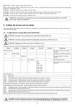
20
6.2
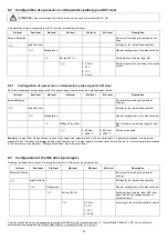
Configuration of a pressure or a temperature probe type at X61 door
ATTENTION:
If the external load controller is set do not connected to terminals X60 or X61.
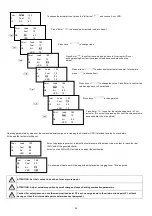
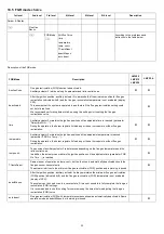
If a modulation probe is connected to the X61 terminal, proceeding as follows:
1st level
2nd level
3rd level
4th level
5th level
6th level
Description
Params & Display
Menu level for making the parameter set-
tings
LoadController
Settings
for
the
internal
load
controller
Configuration
General configuration of the load controller
Ext Inp X61 U/ I
Configuration of external input X61
4…20 mA
2...10 V
0...10 V
0…20 mA
Set the proper value according to the probe
output.
6.2.1
Configuration of a pressure or a temperature probe signal at X61 door
Once the pressure sensor signal type is set, the sensor range must be set as well, proceeding as follows:
1st level
2nd level
3rd level
4th level
5th level
6th level
Description
Params&Display
Menu level for making the parameter
settings
LoadController
Settings
for
the
internal
load
controller
Configuration
General configuration of the load controller
MRange PressSens
End of pressure measuring range for input
X61
0...99.9 bar
0...2000 °C
0...99.9 bar
0...2000 °C
Set the probe value
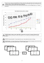
Example:
if a max 10bar Siemens sensor is used, the voltage output signal will be 0 V at 0 bar, while the 10 V signal will correspond to its maximum
pressure 10 bar. If the sensor is replaced with a max 16bar one, the 0 V output signal will correspond to 0 bar, while the 10 V output signal will correspond
to 16bar pressure: the parameter “MRange Press-Sens” has to be set at 16bar.
6.3
Configuration of the X62 door input signal
Following the below route access to the programming levels of the menu by means the Esc
1st level
2nd level
3rd level
4th level
5th level
6th level
Description
Params & Display
Menu level for making the parameter
settings
LoadController
Settings for the internal load controller
Configuration
General configuration of the load controller
Ext Inp X62 U/I
Configuration of external input X62: input
signal on X62 can change setpoint or
control the load
4...20 mA
2...10 V
0…10 V
0…20 mA
According to the external modulator output.
If a boiler second probe is to be connected to terminals (1000 Ohm only), internal functions TL_ThreshOff and DiffIntervTL_SD_On are activated
automatically (see paragraph SETTING FUNCTIONS “TL_ThreshOff” AND “TL_SD_On”).
Summary of Contents for K990A
Page 41: ...PART IV MAINTENANCE 41...
Page 42: ......
Page 43: ......
Page 45: ...Siemens LMV5x Service Manual M12920CC rev 2 1 08 2017...
Page 52: ...8...
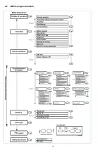
Page 56: ...12 2 2 LMV5x program structure...
Page 83: ...39...
Page 90: ......
Page 91: ......
Page 92: ...Note Specifications and data subject to change Errors and omissions excepted...
Page 94: ...Annex1 Example for motor cable...
Page 95: ......
Page 96: ...Annex 2 Example for sensor cable...
Page 97: ......
Page 98: ......
Page 102: ......


