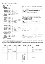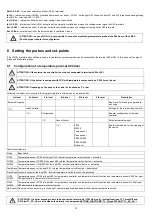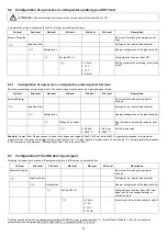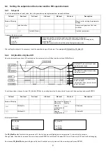
27
9.2
Setting the load points output (burners with no FGR)
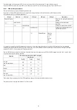
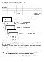
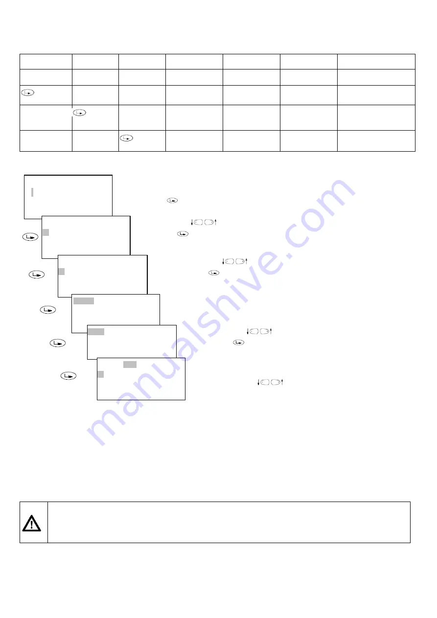
Following the below route access to the programming levels of the menu
1st level
2nd level
3rd level
4th level
5th level
6th level
Description
Params
&
Display
RatioControl
Parameter settings for fuel/
air ratio control
GasSettings
GasSettings
Parameter settings for firing
on Gas or on Oil
CurveParams
At this level, the air/fuel ratio
during operation is to be set.
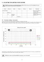
Now it is possible to change Point2 with the next procedure
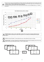
Checking continuously the air excess means of the combustion analyzer, increasing by few degrees* the air damper opening and the VSD if provided.
Then increase by few degrees* the gas butterfly valve (or the fuel actuator). Go on step by step, until the butterfly valve complete opening is reached
(actuator at 90° - see diagram).
The target is to reach the gas butterfly valve maximum with a sufficient excess of air. While progressively increasing the actuator positions, besides
increasing the air quantity the fuel rate must be controlled by means of the valve pressure governor, in order to not exceed the requested maximum flow
rate.
Once the gas butterfly valve maximum opening is reached, adjust the fuel
rate
only acting on the gas valve pressure governor (or on the oil pressure
governor in case of oil).
ATTENTION: as for “increasing by few degrees” it means that the increasing must be performed in order to avoid great excess of
air or defect of air.
Therefore the increasing operation must be performed always checking the flue gas analysis by means of the combustion
analyzer. It is recommended to make increasing while maintaining O2 % between max 7,5% and min 3%.
It is recommended to save new points increasing the burner output at step odf10÷20% load. Measuring the burner output at the flow meter.
In this way, if for any reason, you must interrupt the commissioning and restart it later, you would help yourself.
Point Load 10
/
Fuel 6,7
Man Air 12
VSD
50
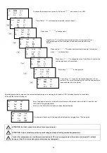
Wait until symbol “\” stops twisting. It indicates that actuators are moving to the displayed position.
When the position is reached it will show the number of the point the LMV5x is at.
Press Enter
to see Point1.
Point Load 10
: 1
Fuel
12
Man Air 6,7
VSD
50
Press “right arrow”
to scroll to the desired point
Press Enter
to change the curve point.
Point Load 100
: 2
Fuel
12
Man Air 6,7
VSD
50
Press “right arrow”
to scroll to the desired point
Press Enter
to change the curve point.
Change
Delete
Select "change" to change the point, or "delete" to cancel it
Follow
Not Follow
Press “right arrow”
to scroll to the desired point
Press Enter
on “Follow”. The actuator moves in real time as the operator
change its setting
Point Load 100
: 2
Fuel
12
Man Air 6,7
VSD
50
The selector will be on Load.
By menas the arrow
scroll to the desired actuator
Summary of Contents for K990A
Page 41: ...PART IV MAINTENANCE 41...
Page 42: ......
Page 43: ......
Page 45: ...Siemens LMV5x Service Manual M12920CC rev 2 1 08 2017...
Page 52: ...8...
Page 56: ...12 2 2 LMV5x program structure...
Page 83: ...39...
Page 90: ......
Page 91: ......
Page 92: ...Note Specifications and data subject to change Errors and omissions excepted...
Page 94: ...Annex1 Example for motor cable...
Page 95: ......
Page 96: ...Annex 2 Example for sensor cable...
Page 97: ......
Page 98: ......
Page 102: ......


