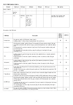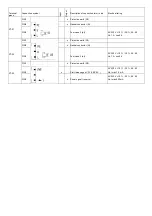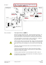
X52
PIN4
x
(functional
earth)
PIN3
x
AC power supply from transformer to
LMV5... system
AC 12 V +10 % / -15 %, 50...60 Hz
PIN2
x
Reference ground (PELV)
PIN1
x
AC power supply from transformer to
LMV5... system
AC 12 V +10 % / -15 %, 50...60 Hz
Terminal
group
Connection symbol
Inpu
t
Out
pu
t
Description of connection termi- nals
Electrical rating
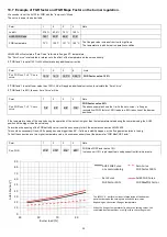
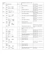
Temperature / pressure controller
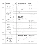
X60
PIN5
x
Functional earth for shield connec- tion
PIN4 x
Reference
ground
PIN3
x
Temperature sensor input Pt / LG- Ni
1000
PIN2
x
Line compensation temperature
sensorPT100
PIN1
x
Temperature sensor input PT100
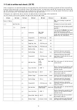
X61
PIN5
x
Functional earth for shield connec- tion
PIN4 x
Reference
ground
PIN3
x
Current input for temperature / pressure
signal 0/4...20 mA
DC 0/4...20 mA
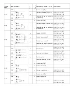
PIN2
x
Voltage input for temperature / pressure
signal DC 0...10 V
DC 0...10 V
PIN1
x
Power supply for temperature / pressure
transmitter
approx. DC 20 V Max. 25 mA
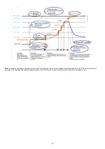
X62
PIN5
x
Functional earth for shield connec- tion
PIN4 x
Reference
ground
PIN3
x
Current input for setpoint or load
DC 0...20 mA
PIN2
x
Voltage input for setpoint or load
DC 0...10 V
PIN1
x
Power supply for setpoint changeo- ver
approx. DC 24 V Max. 2 mA
X63
PIN3
x
Functional earth for shield connec- tion
PIN2
x
Reference
ground
PIN1
x
Current output for burner(LOAD
OUTPUT)
DC 4...20 mA, RLmax = 500 £[
Summary of Contents for K990A
Page 41: ...PART IV MAINTENANCE 41...
Page 42: ......
Page 43: ......
Page 45: ...Siemens LMV5x Service Manual M12920CC rev 2 1 08 2017...
Page 52: ...8...
Page 56: ...12 2 2 LMV5x program structure...
Page 83: ...39...
Page 90: ......
Page 91: ......
Page 92: ...Note Specifications and data subject to change Errors and omissions excepted...
Page 94: ...Annex1 Example for motor cable...
Page 95: ......
Page 96: ...Annex 2 Example for sensor cable...
Page 97: ......
Page 98: ......
Page 102: ......


