8
ConF > Cntr
Here, the type of controller, operating action, setpoint limits and presettings for self-optimization are selected
(
bold
= factory settings)
ConF > rAFC
Activation boiler shock termic protetion
:
RWF55.. can activate the thermal shock protection only on sites where the set-point is lower than 250°C and according to
rAL
parame-
ter
(
bold
= factory settings)
Parameter
Value
Description
CtYP
c
ontroller type
1
2
1 =
3-position controller (open-stop-close)
2 =
continuative action controller
(0 ÷10V
or
4 ÷ 20mA)
CACt
control action
1
0
1 =
heating controller
0 =
cooling controller
SPL
least value of the set-point
range
-1999..
0
..+9999
minimum set-point scale
SPH
maximum value of the set-
point range
-1999..
100
..+999
maximum set-point scale
Self-optimization
0
1
0 =
Free
1 =
Locked
Self-optimization can only be disabled or enabled via the ACS411 setup program.
Self-optimization is also disabled when the parameter level is locked
oLLo
set-point limitation start,
operation limit low
-1999
.... +9999
lower working range limit
oLHi
set-point limitation end,
operation limit high
-1999....
+9999
upper working range limit
Parameter
Value
Description
FnCT
type of contol
0
1
2
t
choose type of range degrees/time
0 =
deactived
1 =
Kelvin degrees/minute
2 =
Kelvin degrees/hour
rASL
ramp rate
0,0 …
999,9
Slope of thermal shock protection (only with functions 1 and 2)
.
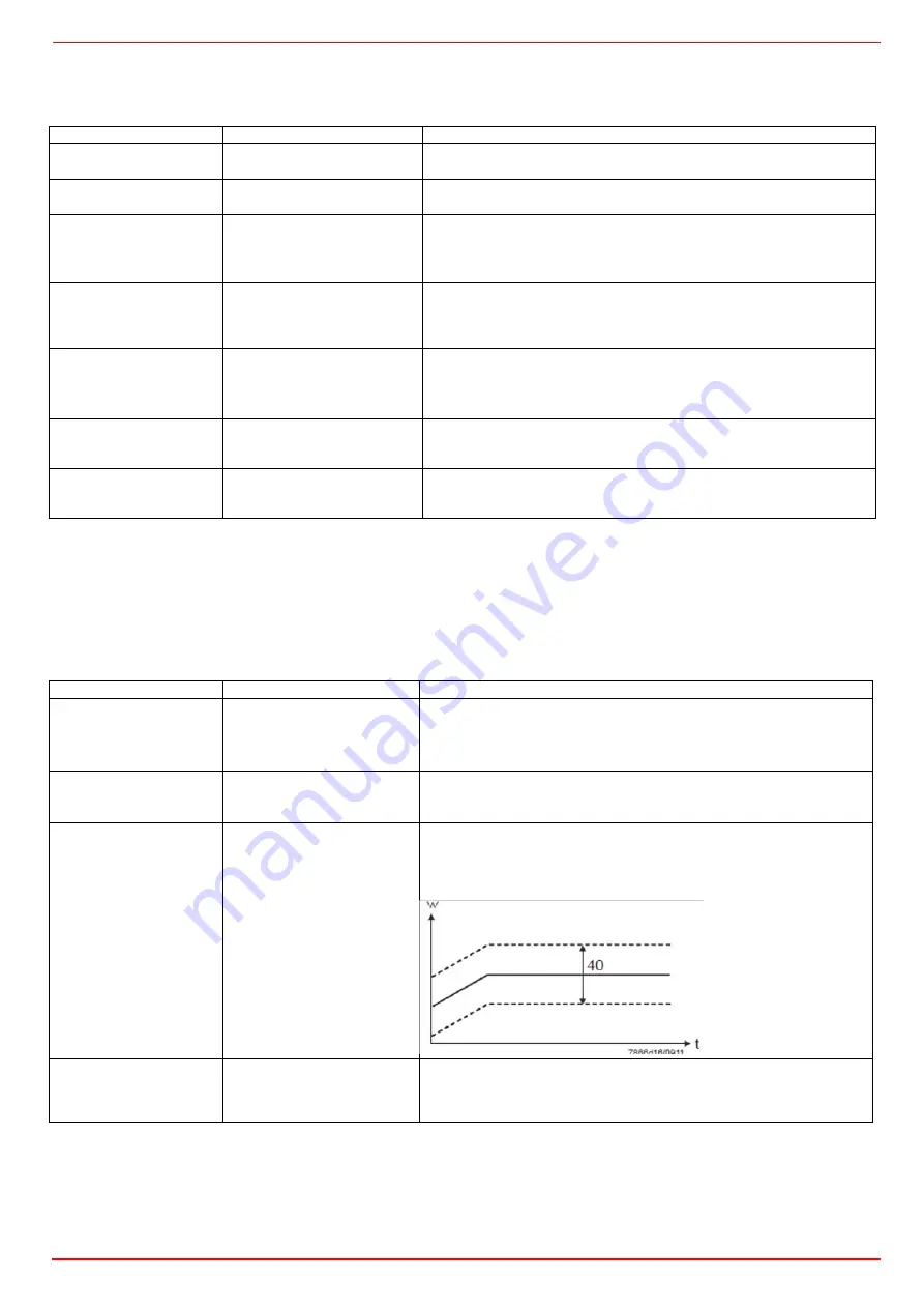
toLP
tolerance band ramp
2 x (HYS1) = 10
…9999
width of tolerance band (in K) about the set-point
0 = tolerance band inactive
rAL
ramp limit
0
…250
Ramp limit. When this value is lower than the temperature set-point, the
RWF controls the output increasing the temp set point step by step accor-
ding to
rASL
. If this is over the temp set point, the control is performed in
cooling
Summary of Contents for KTP1030
Page 25: ...C I B UNIGAS M039207CB 25 Fig 17 Hydraulic diagram 3ID0014 Two or more burners configuration...
Page 46: ...C I B UNIGAS M039207CB 46...
Page 47: ...C I B UNIGAS M039207CB 47...
Page 48: ...C I B UNIGAS M039207CB 48...
Page 49: ...C I B UNIGAS M039207CB 49...
Page 50: ...C I B UNIGAS M039207CB 50 Pumping Unit Electric Wiring Diagrams...
Page 51: ...C I B UNIGAS M039207CB 51...
Page 52: ...C I B UNIGAS M039207CB 52...
Page 55: ...C I B UNIGAS M039207CB 55...
Page 59: ......
Page 74: ......
Page 83: ......
Page 84: ......
Page 85: ...RWF50 2x RWF50 3x User manual M12922CB Rel 1 0 07 2012...
Page 100: ...16 Note Specifications and data subject to change Errors and omissions excepted...
Page 101: ...KM3 Modulator USER MANUAL M12927CA Rel 1 0 10 2020...
Page 102: ...M12927CA MOUNTING 2...
Page 118: ...1 RWF55 5X RWF55 6X User manual M12926CA Rel 0 1 10 2015...
Page 119: ...2 DEVICE INSTALLATION Fixing system Drilling dimensions...
Page 140: ......
Page 141: ...23 Note Specifications and data subject to change Errors and omissions excepted...


