C
.I.B. UNI
GAS
-
M039207C
B
19
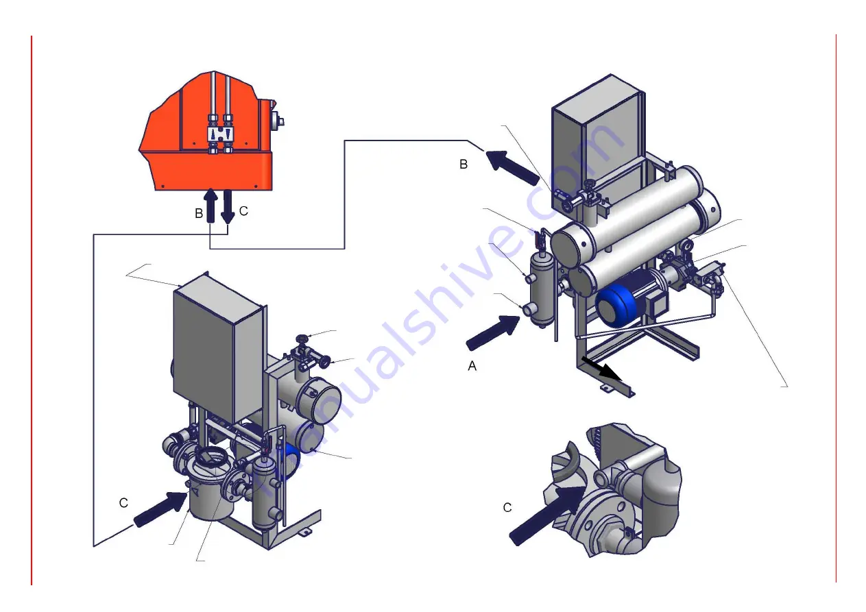
Connecting the burner to the oil pumping unit
Follow the scheme in the picture below to connect the burner to the oil pumping unit. The pump sends the oil coming from the tank to the burner. The pressure governor makes the oil reach the
nozzle at the required pressure, while the excess of oil goes back to the tank. To change the delivery pressure act on the adjusting screw of the delivery pressure governor.
Comb filter
Electric panel
Thermometer
To the burner
Pre-heater drain plug
Return from burner
Filter
Filtro
Pressure governor
Pump
Pressure gauge
Water drain cock
To plug
From the tank
Summary of Contents for KTP1030
Page 25: ...C I B UNIGAS M039207CB 25 Fig 17 Hydraulic diagram 3ID0014 Two or more burners configuration...
Page 46: ...C I B UNIGAS M039207CB 46...
Page 47: ...C I B UNIGAS M039207CB 47...
Page 48: ...C I B UNIGAS M039207CB 48...
Page 49: ...C I B UNIGAS M039207CB 49...
Page 50: ...C I B UNIGAS M039207CB 50 Pumping Unit Electric Wiring Diagrams...
Page 51: ...C I B UNIGAS M039207CB 51...
Page 52: ...C I B UNIGAS M039207CB 52...
Page 55: ...C I B UNIGAS M039207CB 55...
Page 59: ......
Page 74: ......
Page 83: ......
Page 84: ......
Page 85: ...RWF50 2x RWF50 3x User manual M12922CB Rel 1 0 07 2012...
Page 100: ...16 Note Specifications and data subject to change Errors and omissions excepted...
Page 101: ...KM3 Modulator USER MANUAL M12927CA Rel 1 0 10 2020...
Page 102: ...M12927CA MOUNTING 2...
Page 118: ...1 RWF55 5X RWF55 6X User manual M12926CA Rel 0 1 10 2015...
Page 119: ...2 DEVICE INSTALLATION Fixing system Drilling dimensions...
Page 140: ......
Page 141: ...23 Note Specifications and data subject to change Errors and omissions excepted...


