C.I.B. UNIGAS - M039207CB
33
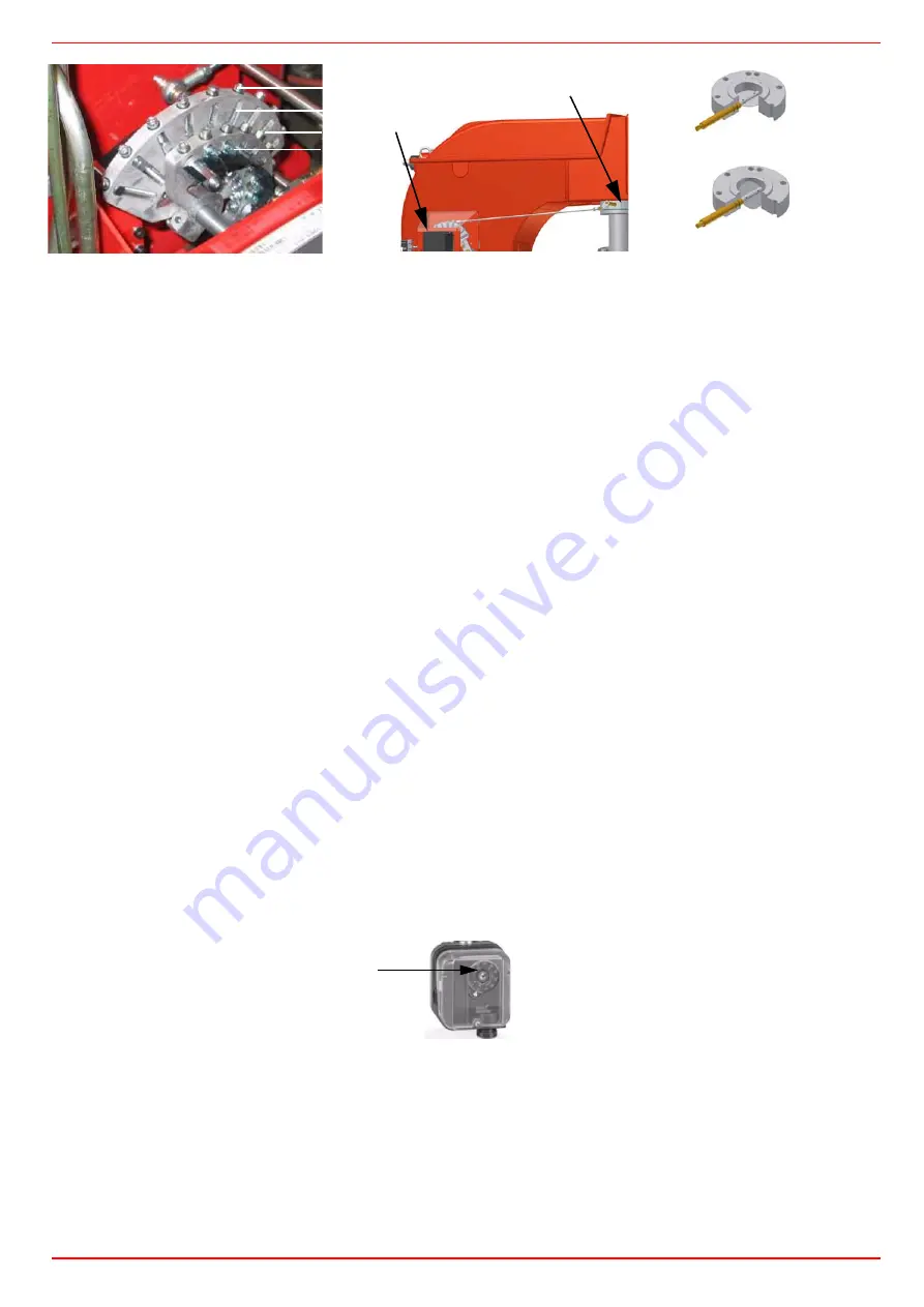
Calibration of air pressure switch
To calibrate the air pressure switch, proceed as follows:
z
Remove the transparent plastic cap.
z
Once air and fuel setting have been accomplished, startup the burner.
z
During the pre-purge phase o the operation, turn slowly the adjusting ring nut
VR
in the clockwise direction (to increase the adju-
sting pressure) until the burner lockout, then read the value on the pressure switch scale and set it to a value reduced by 15%.
z
Repeat the ignition cycle of the burner and check it runs properly.
z
Refit the transparent plastic cover on the pressure switch.
Calibration of minimum gas pressure switch
As for the gas pressure switch calibration, proceed as follows:
z
Be sure that the filter is clean.
z
Remove the transparent plastic cap.
z
While the burner is operating at the maximum output, test the gas pressure on the pressure port of the minimum gas pressure
switch.
z
Slowly close the manual cutoff valve (placed upstream the pressure switch, see gas train installation diagram), until the detected
pressure is reduced by 50%. Pay attention that the CO value in the flue gas does not increase: if the CO values are higher than the
limits laid down by law, slowly open the cutoff valve as to get values lower than these limits.
z
Check that the burner is operating correctly.
z
Clockwise turn the pressure switch adjusting ring nut (as to increase the pressure value) until the burner stops.
z
Slowly fully open the manual cutoff valve.
z
Refit the transparent plastic cover on the pressure switch.
Adjusting the high gas pressure switch (when provided)
To calibrate the high pressure switch, proceed as follows:
z
remove the plastic cover;
z
measure the gas pressure in the network, when flame is off;
z
by means of the adjusting ring nut
VR
, set the value read on step 2, increased by the 30%;
z
replace the plastic cover.
PGCP Gas leakage pressure switch (witn SiemensLDU/Siemens LMV burner control)
z
remove the pressure switch plastic cover;
z
adjust the PGCP pressure switch to the same value set for the minimum gas pressure switch;
z
replace the plastic cover.;
V1
V2
SV1
SV2
SC
SC
VF
butterfly valve open
butterfly valve close
VR
Summary of Contents for KTP1030
Page 25: ...C I B UNIGAS M039207CB 25 Fig 17 Hydraulic diagram 3ID0014 Two or more burners configuration...
Page 46: ...C I B UNIGAS M039207CB 46...
Page 47: ...C I B UNIGAS M039207CB 47...
Page 48: ...C I B UNIGAS M039207CB 48...
Page 49: ...C I B UNIGAS M039207CB 49...
Page 50: ...C I B UNIGAS M039207CB 50 Pumping Unit Electric Wiring Diagrams...
Page 51: ...C I B UNIGAS M039207CB 51...
Page 52: ...C I B UNIGAS M039207CB 52...
Page 55: ...C I B UNIGAS M039207CB 55...
Page 59: ......
Page 74: ......
Page 83: ......
Page 84: ......
Page 85: ...RWF50 2x RWF50 3x User manual M12922CB Rel 1 0 07 2012...
Page 100: ...16 Note Specifications and data subject to change Errors and omissions excepted...
Page 101: ...KM3 Modulator USER MANUAL M12927CA Rel 1 0 10 2020...
Page 102: ...M12927CA MOUNTING 2...
Page 118: ...1 RWF55 5X RWF55 6X User manual M12926CA Rel 0 1 10 2015...
Page 119: ...2 DEVICE INSTALLATION Fixing system Drilling dimensions...
Page 140: ......
Page 141: ...23 Note Specifications and data subject to change Errors and omissions excepted...


