11
APPENDIX: PROBES CONNECTION
To assure the utmost comfort, the control system needs reliable information, which can be obtained provided the sensors have been installed correctly.
Sensors measure and transmit all variations encountered at their location.
Measurement is taken based on design features (time constant) and according to specific operating conditions.With wiring run in raceways, the sheath
(or pipe) containing the wires must be plugged at the sensor's terminal board so that currents of air cannot affect the sensor's measurements.
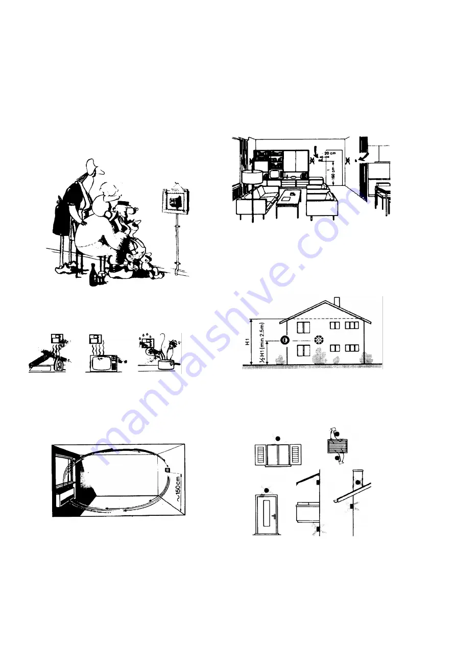
Ambient probes (or ambient thermostats)
Installation
T
he sensors (or room thermostats) must be located in
reference rooms in a position where they can take real temperature
measurements without being affected by
foreign factors.
Outside probes (weather)
Installation
In heating or air-conditioning systems featuring adjustment in
response to outside temperature, the sensor's positioning is of
paramount importance.
It's good to be admired …even better to be effective
Heating systems: the room sensor must not be installed in rooms
with heating units complete with thermostatic valves. Avoid all
sources of heat foreign to the system.
General rule:
on the outer wall of the building where the living rooms
are, never on the south-facing wall or in a position where they will be
affected by morning sun. If in any doubt, place them on the north or
north-east façade.
Location
On an inner wall on the other side of the room to heating unitsheight
above floor 1.5 m, at least 1.5 m away from external sources of heat
(or cold).
Installation position to be avoided
near shelving or alcoves and recesses, near doors or win-dows,
inside outer walls exposed to solar radiation or currents of cold air, on
inner walls with heating system pipes, domestic hot water pipes, or
cooling system pipes running through them.
Positions to be avoided
Avoid installing near windows, vents, outside the boiler room, on
chimney breasts or where they are protected by balconies, cantilever
roofs.
The sensor must not be painted (measurement error).
Summary of Contents for KTP1030
Page 25: ...C I B UNIGAS M039207CB 25 Fig 17 Hydraulic diagram 3ID0014 Two or more burners configuration...
Page 46: ...C I B UNIGAS M039207CB 46...
Page 47: ...C I B UNIGAS M039207CB 47...
Page 48: ...C I B UNIGAS M039207CB 48...
Page 49: ...C I B UNIGAS M039207CB 49...
Page 50: ...C I B UNIGAS M039207CB 50 Pumping Unit Electric Wiring Diagrams...
Page 51: ...C I B UNIGAS M039207CB 51...
Page 52: ...C I B UNIGAS M039207CB 52...
Page 55: ...C I B UNIGAS M039207CB 55...
Page 59: ......
Page 74: ......
Page 83: ......
Page 84: ......
Page 85: ...RWF50 2x RWF50 3x User manual M12922CB Rel 1 0 07 2012...
Page 100: ...16 Note Specifications and data subject to change Errors and omissions excepted...
Page 101: ...KM3 Modulator USER MANUAL M12927CA Rel 1 0 10 2020...
Page 102: ...M12927CA MOUNTING 2...
Page 118: ...1 RWF55 5X RWF55 6X User manual M12926CA Rel 0 1 10 2015...
Page 119: ...2 DEVICE INSTALLATION Fixing system Drilling dimensions...
Page 140: ......
Page 141: ...23 Note Specifications and data subject to change Errors and omissions excepted...


