16
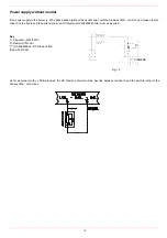
When wishing to monitor the test, install a pressure gauge ranged to that of the pressure supply point
PA
(Fig. 8). If the test cycle is
satisfactory, after a few seconds the consent light
LC
(yellow) comes on. In the opposite case the lockout light
LB
(red) comes on. To
restart it is necessary to reset the appliance by pressing the illuminated pushbutton
LB
.
Once the train is installed, connect the gas valves group plug and the gas pressure switch one (on the valve group as well). Pay atten-
tion not to exchange them.
Electrical connections
To execute the electrical connections, proceed as follows:
1
find the pulg or the plugs, according to the model, that comes out from the burnrer:
7 pins plug for power supply (all models)
4 pins plug;
7 pins plug (for MD - fully modulating burners);
2
execute the electrical connections to the plugs, according to hte burner model (see next paragraph);
3
now the burner is ready to start up.
Connectors identification
ATTENTION:
once the gas train is mounted according to the diagram, the gas proving test mus be performed, according to
the procedure set by the laws in force.
Respect the basic safety rules. make sure of the connection to the earthing system. do not reverse the phase
and neutral connections. fit a differential thermal magnet switch adequate for connection to the mains.
ATTENTION: before executing the electrical connections, pay attention to turn the plant’s switch to OFF and be
sure that the burner’s main switch is in 0 position (OFF) too. Read carefully the chapter “WARNINGS”, and the
“Electrical connections” section.
WARNING: if the cable that connects the thermostats and the control box should be longer than 3 meters, insert a
sectioning relay following the attached electrical wiring diagram..
.
The burner is fitted with a bridge between terminals T6 and T8 on the 4-poles plug-TAB (external side link, male
connector); if the TAB high/low flame thermostat must be connected, remove the bridge between terminals,
before connecting the thermostat.
IMPORTANT: before operating the burner, be sure all connectors are linked as indicated in the diagrams.
Burner power supply connector
HIGH/LOW flame connector
7-pins connector
7-pins and 4-pins connectors


