22
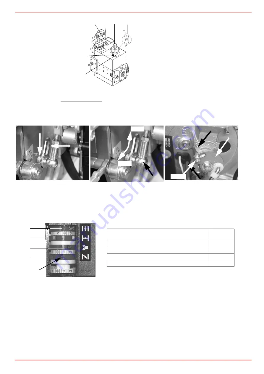
slackening the locking screw
VB
by a number of turns. By unscrewing the regulator
RP
the valve opens, screwing the valve closes.
6
To adjust the air flow rate, slacken the nut
RA
(see picture) and move the lever
VRA
through the slot as shown in see picture, to
increase or decrease the air rate, until the desired rate is obtained; lock then the nut
RA
in this position.
7
Drive the burner to the low flame operation, by the
TAB
boiler thermostat.To eventually change the gas flow rate, slacken the
screw
V1
(see picture below) and set the opening angle of the buttefly valve rotating the round plate
C
(turn clockwise to decrease
the gas rate or counterclockwise to increase it). The index
S
shows the opening angle of the butterfly valve.
8
If it was necessary to change the low flame burner output, act on the actuator related cam. Then, check the gas flow rate and
repeat from step 7.
As for the setting, refer to this correspondence table. On this actuator, the manual control of the air damper is not provided; the setting
of the cams is carried out working with a screwdriver on the
VS
screw placed internally to the cam.
Fig. 12
Fig. 13
Fig. 14
C
VS T(VR)
VB
VSB
RP
Fig. 11
Dungs Multibloc MB-DLE
RA
CA
VRA
MIN
MAX
V1
C
S
I
II
III
IV
VS
BERGER
STA4.5B0.37/
High flame position (set to 90°)
I
Low flame and ignition position
IV
Stand-by position (set to 0°)
II
Not used
III


