C.I.B. UNIGAS - M039196CC
32
At least once a year carry out the maintenance operations listed below. In the case of seasonal servicing, it is recommended to carry
out the maintenance at the end of each heating season; in the case of continuous operation the maintenance is carried out every 6
months.
ROUTINE MAINTENANCE
z
Clean and examine the oil filter cartridge and replace it if necessary.
z
Examine the condition of the oil flexible tubing and check for possible leaks.
z
Check and clean if necessary the oil heaters and the tank, according to the fuel type and its use; remove the heaters flange fixing
nuts and remove the heaters from the tank: clean by using steam or solvents and not metallic things.
z
Clean and examine the filter inside the oil pump. Filter must be thoroughly cleaned at least once in a season to ensure correct
working of the fuel unit. To remove the filter, unscrew the four screws on the cover. When reassemble, make sure that the filter is
mounted with the feet toward the pump body. If the gasket between cover and pump housing should be damaged, it must be repla-
ced. An external filter should always be installed in the suction line upstream of the fuel unit.
z
Remove and clean the combustion head (page 32).
z
Examine and clean the ignition electrodes, adjust and replace if necessary (see page 33).
z
Examine and clean the detection probe, adjust and replace if necessary (see page 34).
z
Examine the detection current (see page 34).
z
Remove and clean (page 34) the heavy oil nozzle
(Important: use solvents for cleaning, not metallic tools)
and at the end of
the maintenance procedures, after replacing the burner, turn it on and check the shape of the flame; if in doubt replace the nozzle.
Where the burner is used intensively it is recommended to replace the nozzle as a preventive measure, at the begin of the opera-
ting season.
z
Clean and grease joints and rotating parts.
IMPORTANT:Remove the combustion head before checking the ignition electrodes.
Removing the combustion head
z
Remove the cover H.
z
Slide the UV photoelectric cell out of its housing.
z
Unscrew the oil connections E (Fig. 28) connecting the flexible pipes to the lance L and remove the whole assembly as shown in
Fig. 28-Fig. 29.
z
clean the combustion head by means of a vacuum cleaner; to scrape off the scale use a metallic brush.
Note: to replace the combustion head reverse the procedure described above.
WARNING: ALL OPERATIONS ON THE BURNER MUST BE CARRIED OUT WITH THE MAINS DISCONNECTED AND
THE FUEL MANAUL CUTOFF VALVES CLOSED!
ATTENTION: READ CAREFULLY THE “WARNINGS” CHAPTER AT THE BEGINNIG OF THIS MANUAL..
CAUTION: avoid the contact of steam, solvent and other liquids with the electric terminals of the resistor.
On flanged heaters, replace the seal gasket before refitting it.
Periodic inspections must be carried out to determine the frequency of cleaning.
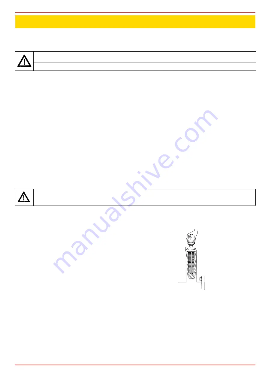
Self-cleaning filter
Fitted only for oil viscosity >110 cSt @ 50 °C. Periodically turn the knob to clean the
filter.
PART III: MAINTENANCE
Summary of Contents for PN510
Page 19: ...C I B UNIGAS M039196CC 19 Fig 14 Hydraulic diagram 3ID0014 Two or more burners configuration ...
Page 37: ...C I B UNIGAS M039196CC 37 ...
Page 45: ......
Page 46: ......
Page 47: ......


