5
Setting the kind of sensor to be connected to the device:
push
the
Enter
button: on the lower display (green)
Opr
appears. Using the
up and down arrows
find
ConF.
Push
Enter
to confirm.
Now on the green display the group
InP
appears. Push
Enter
and
InP1
is displaied. Enter to confirm.
You are inside
InP1
; the green display shows
Sen1 (sensor type)
, while the red display shows the chosen sensor
code
Push
Enter
to enter the
Sen1
parameter, then choose the desired sensor using the
arrows.
Push
Enter
to confirm
and
ESC
to escape.
Once selected the sensor, you can modify all the other parameters using
up and down arrows
according to the
tables here below.
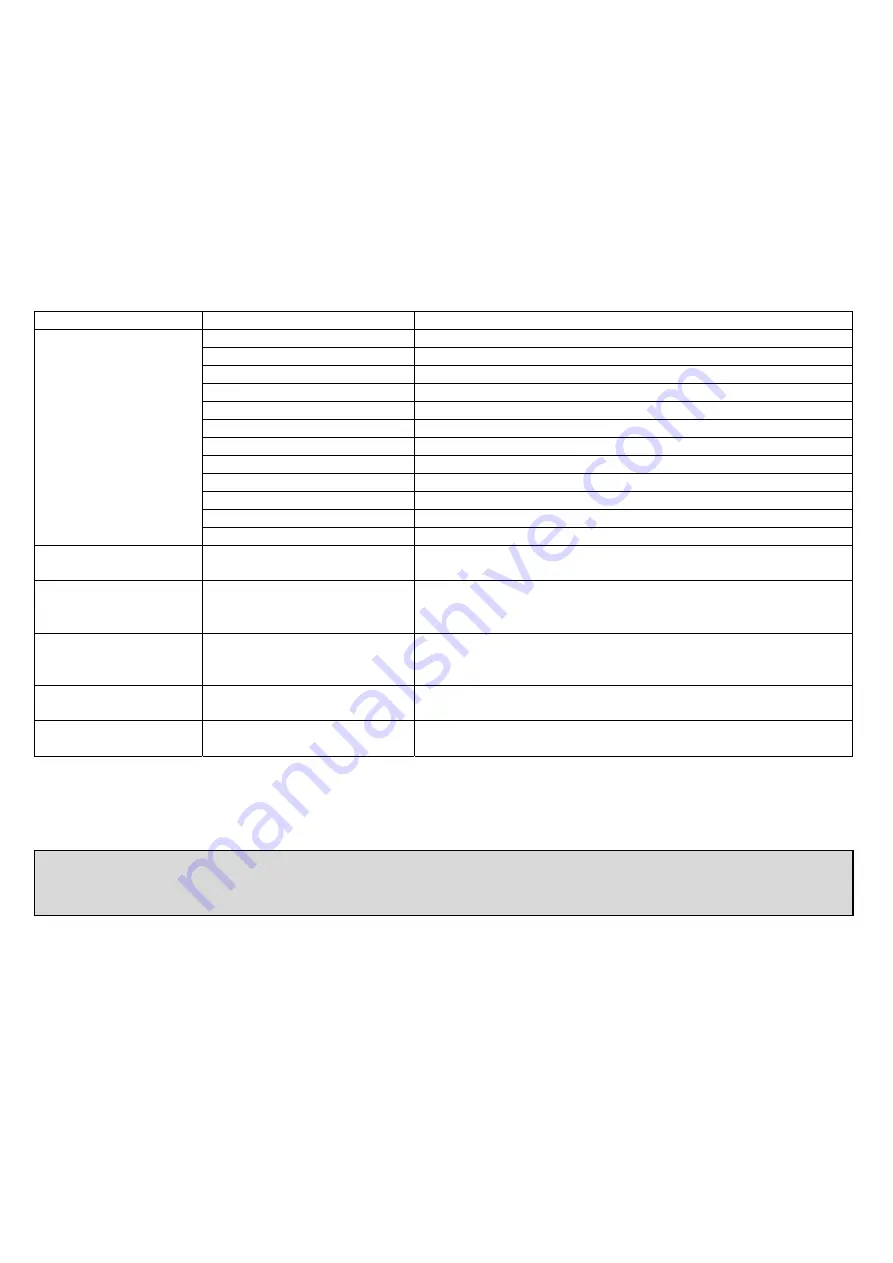
ConF > InP >InP1
Parameter Value
Description
SEn1
type of sensor for
analog input 1
1
Pt100 3 fili
2
Pt100 2 fili
3
Pt1000 3 fili
4
Pt1000 2 fili
5
Ni1000 3 fili
6
Ni1000 2 fili
7
0 ÷ 135 ohm
15
0 ÷ 20mA
16
4 ÷ 20mA
17
0 ÷ 10V
18
0 ÷ 5V
19
1 ÷ 5V
OFF1
sensor offset
-1999..
0
.. +9999
Using the measured value correction (offset), a measured
value can be corrected to a certain degree, either up or down
SCL1
scale low level
-1999..
0
.. +9999
In the case of a measuring transducer with standard signal, the
physical signal is assigned a display value here
(for input ohm, mA, V)
SCH1
scale high level
-1999..
100
.. +9999
In the case of a measuring transducer with standard signal, the
physical signal is assigned a display value here
(for input ohm, mA, V)
dF1
digital filter
0…
0,6
…100
Is used to adapt the digital 2nd order input filter
(time in s; 0 s = filter off)
Unit
temperature unit
1
2
1 = degrees Celsius
2 = degrees Fahrenheit
(
bold
= factory settings)
Remark:
RWF50.2 e RWF50.3 cannot be connected to thermocouples.
If thermocouples have to be connected, convert the signal to a 4-20 mA one and set the RWF accordingly.
Summary of Contents for RN510
Page 39: ......
Page 54: ......
Page 63: ......
Page 64: ......
Page 65: ...RWF50 2x RWF50 3x User manual M12922CB Rel 1 0 07 2012...
Page 80: ...16 Note Specifications and data subject to change Errors and omissions excepted...
Page 81: ...KM3 Modulator USER MANUAL M12927CA Rel 1 0 10 2020...
Page 82: ...M12927CA MOUNTING 2...
Page 98: ...1 RWF55 5X RWF55 6X User manual M12926CA Rel 0 1 10 2015...
Page 99: ...2 DEVICE INSTALLATION Fixing system Drilling dimensions...
Page 120: ......
Page 121: ...23 Note Specifications and data subject to change Errors and omissions excepted...
Page 130: ...OFF...
Page 131: ......
Page 132: ......
Page 133: ......
Page 134: ......
Page 135: ......
Page 136: ......
Page 137: ......
Page 138: ......


