26
6
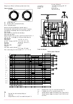
Start the burner up by means of the thermostat series and wait unitl the pre-purge phase comes to end and that burner starts up;
7
drive the burner to high flame stage, by means fo the thermostat
TAB
(high/low flame thermostat - see Wiring diagrams), as far as
fully-modulating burners, see related paragraph.
8
Then move progressively the microswitch to higher values until it reaches the high flame position; always check the combustion
values (see next steps).
9
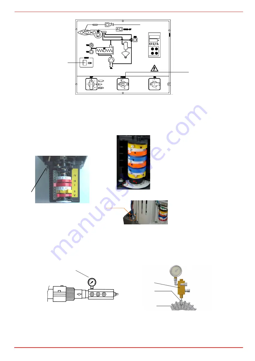
the nozzle supply pressure is already factory-set and must not be changed. Only if necessary, adjust the supply pressure as fol-
lows (see related paragraph); insert a pressure gauge into the port shown on Fig. 18 and act on on the pump adjusting screw
VR
(see Fig. 17) as to get the nozzle pressure at 25bar (see diagram on page 22).
10 in order to get the maximum oil flow rate, adjust the pressure (reading its value on the
PG
pressure gauge): checking always the combu-
stion parameters, the adjustment is to be performed by means of the
SV
adjusting cam screw
V
(see picture) when the cam has reached
the high flame position.
11 To adjust the
air flow rate in the high flame stage
, loose the
RA
nut and screw
VRA
as to get the desired air flow rate: moving
the rod
TR
towards the air damper shaft, the air damper opens and consequently the air flow rate increases, moving it far from the
Berger STM30
Siemens SQM40
Actuator cams
I
High flame
II
Stand-by and Ignition
III
Low flame
Fig. 20
Fig. 22
A
C
B
MAN-AUTO
mensions
Dimensions in
SQM4...
I
III
II
IV
V
VI
VI
V
IV
II
III
I
MAN-AUTO
Pressure gauge port
RP
PG
V
SV


