5
Start-up procedure
1
Turn the burner on according to the following:
z
ual fuel burners: choose the requested fuel by means of the related control panel switch
z
one fuel burners: turn the burner on by means of the burner main switch (placed on the burner control panel)
2
the LMV controller starts the system test cycle: the AZL display shows the
System Test
message; at the end of the test, it shows
the main page and the system stops (the safety chain is open) waiting for the startup enabling signal (standby - Program phase no.
12)
3
check the fan motor rotation;
4
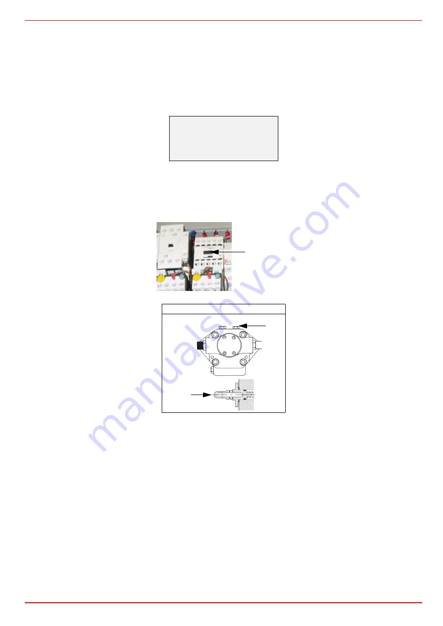
(light/heavy oil burners) with the electrical panel open, prime the oil pump acting directly on the related
CP
contactor (see next pic-
ture): check the pump motor rotation and keep pressing for some seconds until the oil circuit is charged;
5
bleed the air from the
M
pressure gauge port (see next picture) by loosing the cap without removing it, then release the contactor.
6
make the safety chain enabling the system to start up
7
the combustion cycle starts:
- Prepurging
(program phase no.30)
- Driving to ignition position
(program phase no.36)
- Ignition position
(program phase no.38)
- Fuel
(the fuel solenoid valves open)
- Flame
(the flame lights up)
- Driving to low flame
(the actuator drives to low flame).
NOTE:
the
C
and
A
, on the .
Once the ignition cycle ends, the main page is shown:
Suntec T..
Main page
Setpoint 80°C
Act value
78°C
Fuel GAS
CP
M
VR
Summary of Contents for RX1025.1
Page 41: ......
Page 42: ......
Page 43: ......
Page 45: ...User manual Siemens LMV 5x M12914CA Rev 0 03 2008...
Page 46: ......
Page 57: ......
Page 58: ......
Page 59: ......
Page 62: ...Annex1 Example for motor cable...
Page 63: ......
Page 64: ...Annex 2 Example for sensor cable...
Page 65: ......
Page 66: ......
Page 70: ......


