PART I: SPECIFICATIONS
5
Gas operation:
the gas coming from the supply line passes through filter, gas valves and pressure regulator. This one forces the pres-
sure in the utilisation limits. The electric actuator , that moves proportionally the air damper and the gas butterfly valve, uses an adju-
sting cam with variable shape. This one allows the optimisation of the gas flue values, as to get an efficient combustion. The
combustion head positioning determines the burner’s output. The combustion head determines the energetic quality and the geometry
of the flame. Fuel and comburent are routed into separated ways as far as the zone of flame generation (combustion chamber).
The control panel , placed on the burner’s front side, shows each operating stage.
Gas categories and countries of application
(*) Premix type ...N burners are not enabled to work with these gas categories.
The above gas groups can be combined according to the standard EN437:2021 and national situation of countries.
Fuel
Countries
Group
AL, AT, BE, BG, CH, CY, DE, DK, EE, ES, FI, FR, GB, GR, HR, HU,
IE, IS, IT, LT, LU, LV, MK, MT, NO, NL, PL, PT, RO, SE, SI, SK, TR
H
L (*)
E
2R (*)
EK (*)
Er (*)
LL (*)
E (R)
DANGER! The burner must be used only with the fuel specified in the burner data
plate.
PART I: SPECIFICATIONS
1
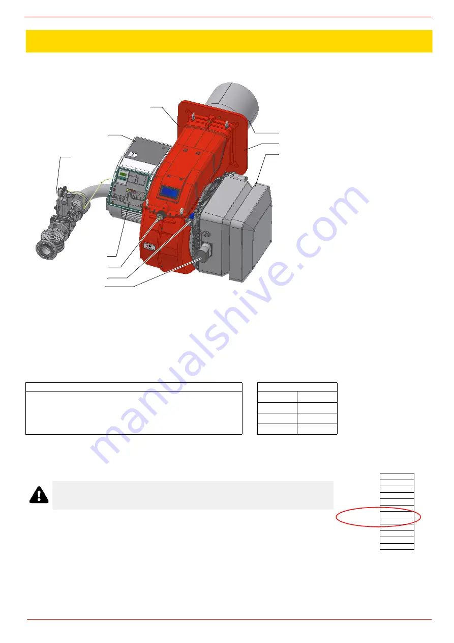
Control panel with startup switch
2
Gas train
3
Electrical panel
4
Cover
5
Blast tube + Combustion head
6
Flange
7
Silencer
8
Actuator
9
Air pressure switch
Combustion head adjusting ring nut
5
6
7
1
10
9
8
3
2
4
Type --
Model
--
Year --
S.Number --
Output --
Oil Flow
--
Fuel
--
Category --
Gas Pressure
--
Viscosity --
El.Supply --
El.Consump. --
Summary of Contents for RX1025.1
Page 41: ......
Page 42: ......
Page 43: ......
Page 45: ...User manual Siemens LMV 5x M12914CA Rev 0 03 2008...
Page 46: ......
Page 57: ......
Page 58: ......
Page 59: ......
Page 62: ...Annex1 Example for motor cable...
Page 63: ......
Page 64: ...Annex 2 Example for sensor cable...
Page 65: ......
Page 66: ......
Page 70: ......


