background image

56

Summary of Contents for RX92R

Page 1: ...06 2021 BURNERS BRUCIATORI BRULERS BRENNER QUEMADORES MANUAL OF INSTALLATION USE MAINTENANCE RX92R RX92 1 RX512R RX512 1 RX515 1 RX520 1 Gas burners Microprocessor controlled LMV2x 3x With flue gas r...

Page 2: ...e employed exclusively for the use for which it was designed Before connecting the burner make sure that the unit rating is the same as delivery mains electricity gas oil or other fuel Observe caution...

Page 3: ...ixtures DIRECTIVES AND STANDARDS Gas burners European directives Regulation 2016 426 UE appliances burning gaseous fuels 2014 35 UE Low Tension Directive 2014 30 UE Electromagnetic compatibility Direc...

Page 4: ...quipment of machi nes EN 60335 2 Electrical equipment of non electric appliances for house hold and similar purposes Safety requirements Burner data plate For the following information please refer to...

Page 5: ...ed by servomotors according to load curves in order to achieve the correct proportion between fuel and air flows and to optimize flue gas parameters The adjustable combustion head can improve the burn...

Page 6: ...andard Y Special 7 EQUIPMENT 1 2 gas valves gas proving system 8 2 gas valves gas proving system maximum gas pressure switch 8 GAS CONNECTION 50 Rp2 65 DN65 80 DN80 100 DN100 9 MICRO PROCESSOR CONTROL...

Page 7: ...Hi 34 02 MJ Stm3 for L P G net calorific value Hi 93 5 MJ Stm3 Note2 Maximum gas pressure 360 mbar with Dungs MBDLE 500 mbar with Siemens VGD or Dungs MultiBloc MBE Minimum gas pressure see gas curve...

Page 8: ...5 390 490 493 928 506 1634 1085 439 261 291 228 447 360 464 M12 424 280 310 300 790 148 642 942 353 649 228 185 478 55 481 170 200 549 9 131 RX92 1 50 1410 1520 135 35 550 100 420 530 493 928 506 1274...

Page 9: ...12 424 280 310 300 790 148 642 942 353 649 131 9 549 200 170 481 55 478 185 228 TIPO DN A AS A AL AA AD AN AP B BS B BL BB C CC D E F G H I J K L M N O min O max P Q R S U V W XH XG XF XE XD XC XB XA...

Page 10: ...eed with Cib Unigas VISTA A A 766 530 222 845 969 603 529 517 1573 1043 611 35 487 149 270 496 494 292 330 117 1633 524 60 515 M 4 1 552 390 390 P H 390 540 390 540 9 P225 P151 P195 45 2 2 5 FGR Flang...

Page 11: ...lengths must be agreed with Cib Unigas VISTA A A 766 530 222 845 969 603 529 650 1573 1044 611 35 487 149 270 496 494 292 117 1634 524 59 509 14 M 552 390 390 P400 390 540 390 540 9 P225 P151 P195 45...

Page 12: ...t tube lengths must be agreed with Cib Unigas A 766 530 222 845 969 603 529 650 1573 1043 611 35 487 149 270 496 494 292 385 383 117 1633 524 60 515 14 M 552 390 390 P425 390 540 390 540 9 P225 P151 P...

Page 13: ...tube lengths must be agreed with Cib Unigas 532 256 650 845 969 270 502 266 772 P 360 494 611 652 222 117 25 149 484 294 1105 1635 530 P 151 P 225 9 P 195 45 2 2 5 390 540 390 540 390 P370 552 390 M1...

Page 14: ...as valve Then subtract the backpressure The result is called pgas Draw a vertical line matching the furnace input value 600kW in the example quoted on the x axis as far as intercepitng the network pre...

Page 15: ...n range of the machine On this diagram the maximum output point is usually reached by adjsuting the combustion head to its MAX position see paragraph Adjusting the combustion head the minimum output p...

Page 16: ...wering percentage Thermal load MW m3 RX512R Depowering percentage RX512 1 Thermal load MW m3 Depowering percentage RX512 1Depowering percentage Thermal load MW m3 RX515 1 Depowering percentage Thermal...

Page 17: ...ead the minimum output point is reached setting the combustion head to its MIN position During the first ignition the combustion head is set in order to find a compromise between the burner output and...

Page 18: ...ical specifications Measuring gas pressure in the combustion head In order to measure the pressure in the combustion head insert the pressure gauge probes one into the combustion chamber s pressure ou...

Page 19: ...ms refer to natural gas with a calorific value of 8125 kcal Stm3 15 C 1013 mbar and a density of 0 714 kg Stm3 The values in the diagrams refer to GPL with a calorific value of 22300 kcal Stm3 15 C 10...

Page 20: ...ns must be carried out with appropriate resources and qualified personnel ATTENTION Use intact and correctly dimensioned hoisting equipment conforms to the local regulations and health and safety regu...

Page 21: ...agram In case the burner must be coupled with boilers with a combustion chamber smaller in dia meter or shorter than those described in the diagram please contact the supplier to verify that a correct...

Page 22: ...ore executing the connections to the gas pipe network be sure that the manual cutoff valves are closed ATTENTION it is recommended to mount filter and gas valves to avoid that extraneous material drop...

Page 23: ...UCIATORE 185 501939 PGMAX PGCP PGMI EV1 EV2 S EV2 EV1 PGMAX PGMIN VD R PGCP VD V VD V VD R PS PS pressure sensor Gas filter Example of gas train MBE A A C B B C 1 Mount flange into pipe systems Use ap...

Page 24: ...pressure switches set to 20 of the setpoint 2 Mounting on pipe Sensor position 5x DN according to MBE Pipe fitting with female thread size mount sensor with seal observe torque 3 The pressure sensor i...

Page 25: ...e safety valve during maintenance operation SA SA TP D BS SKP1 SKP2 SIEMENS VGD Mounting positions TP Siemens VGD con SKPx Example of gas train Gas filter PGCP PGMIN PGMAX T VR Performance range mbar...

Page 26: ...h a flame retardant cable with a section suitable to the installed power see electrical diagram enclo sed paying attention to the voltage values printed on the burner plate Always check in advance the...

Page 27: ...ly it is necessary to modify the electrical connections into the terminal box of the electric motor and replace the overload tripped relay Note on electrical supply In the case where the power supply...

Page 28: ...E MACHINE EXCEPT FOR ITS MAINTENANCE TO SECURE THE MACHINE ACT ON THE ISOLATOR SWITCH IN CASE OF ANOMALIES THAT REQUIRED A SHUT DOWN OF THE BURNER IT S POSSIBLE TO ACT ON THE AUXILIARY LINE SWITCH LOC...

Page 29: ...test is performed the proving system LED turns on At the end of the test the burner staring cycle begins in case of leakage in a valve the gas proving system stops the bur ner and the lamp B1 turns o...

Page 30: ...LMV related manual Check that the combustion parameters are in the suggested limits Check the flow rate measuring it on the counter or if it was not possible verifying the combustion head pressure by...

Page 31: ...ck that the combustion parameters are within the recommended limits Check the flow rate by measuring it at the meter or if this is not possible by checking the pressure in the combustion head with a d...

Page 32: ...ressing the two keys contemporarly the code message will appear by entering the proper password it is possible to access the Service mode Info and Enter keys Used for Info and Service menues Used as E...

Page 33: ...a OEM Service Info Fase Funzione Function Ph00 Fase blocco Lockout phase Ph01 Fase di sicurezza Safety phase Ph10 t10 tempo raggiungimento posizione riposo t10 home run Ph12 Pausa Standby stationary P...

Page 34: ...t62 massimo tempo bassa fiamma funzionamento 2 in preparazione per spegnimento verso bassa fiamma t62 max time low fire operation 2 prepa ring for shutdown traveling to low fire Ph70 t13 tempo postcom...

Page 35: ...hows some basic parameters as 5 Example choose parameter 102 to show the date the display shows parameter 102 flashing on the left and characters _ _ on the right 6 press InFo for 1 3 seconds the date...

Page 36: ...and find out the fault in the Error table To perform the reset press InFo for one second The unit displays an event which does not lead to shutdown The display shows current error code c alternating...

Page 37: ...revious paragraphs about the progressive burners Go on adjusting the burner as described before paying attention to use the CMF switch intead of TAB The CMF position sets the oprating stages to drive...

Page 38: ...requires PS 10 40 or PS 50 200 Outlet pressure MIN 10 25 50 75 MAX PS 10 40 4 mbar 0 4 kPa 2 w c 10 mbar 1 0 kPa 4 w c 25 mbar 2 5 kPa 10 w c 50 mbar 5 0 kPa 20 w c 75 mbar 7 5 kPa 30 w c 100 mbar 10...

Page 39: ...by means of the adjusting ring nut VR set the value read increased by the 30 if the maximum pressure switch is mounted downstream the gas governor gas valves group and upstream the butterfly valve li...

Page 40: ...The diffuser position is factory set as shown in figure A x 10 mm Depending on the boiler application it is possible to act on the holes figure B to improve the flame stability and NOx CO emission va...

Page 41: ...if necesssary Remove and clean the combustion head Examine and clean the ignition electrodes adjust and replace them if necessary Examine and clean the detection electrode photoelement according to t...

Page 42: ...Note to replace the combustion head reverse the procedure described above having care to place correctly the O ring OR between burner and gas manifold Attention before adjusting the combustion head tu...

Page 43: ...electrodes to contact metallic parts blast tube head etc other wise the boiler s operation would be compromised Check the electrodes position after any intervention on the combustion head ATTENTION a...

Page 44: ...the outside and remove the combustion head D 6 loose the screw of th eignition electrodes support E 7 remove the electrodes and replace them paying attention to the measures showed in figure F G 8 re...

Page 45: ...ection current with electrode natural gas To check the detection signal follow the scheme in the picture below If the signal is less than the value indicated check the position of the detection electr...

Page 46: ...mance The owner makes the decision whether to finish using the burner or replacing and disposing of it based on the actual state of the appliance and any repair costs The use of the burner for other p...

Page 47: ...itch functions and links Burner control damaged Replace burner control BURNER LOCKS OUT WITHOUT ANY GAS FLOW Gas valves don t open Check voltage on valves if necessary replace valve or the burner cont...

Page 48: ...a L Galvani 9 35011 Campodarsego PD ITALY Tel 39 049 9200944 Fax 39 049 9200945 9201269 web site www cibunigas it e mail cibunigas cibunigas it Note specifications and data subject to change Errors an...

Page 49: ...Service manual AZL2x LMV2x 3x Burner Management System M12916CD Rev 3 4 03 2023...

Page 50: ...900 Process data 32 Actuators references 33 Gas proving system 33 Air fuel curve points 33 COMMISSIONING THE BURNER 34 Warm setting 38 Cold setting 39 BURNER STARTUP WITH LMV2x ALREADY PROGRAMMED 40...

Page 51: ...CTIONS FOR BURNERS z The burner should be installed in a suitable room with ventilation openings complying with the requirements of the regulations in force and sufficient for good combustion z Only b...

Page 52: ...ditions such as the development of toxic or explosive mixtures DIRECTIVES AND STANDARDS Gas burners European directives Directive 2009 142 EC Gas Appliances Directive 2006 95 EC on low voltage Directi...

Page 53: ...apparatus EN 50165 Electrical equipment of non electric appliances for household and similar purposes Safety requirements UNI EN 746 2 Industrial thermoprocessing equipment Burner data plate For the...

Page 54: ...forms all the burner control functions and of the Siemens AZL local programming unit that interfaces the system with the user Keys 1 Burner 2 AZL2 3 Air actuator 4 Fuel actuator 5 LMV2 User interface...

Page 55: ...ice mode Info and Enter keys Used for Info and Service menues Used as Enter key in the setting modes Used as Reset key in the burner operation mode Used to enter a lower level menu Key Used to decreas...

Page 56: ...8 Parameters level heating engineer...

Page 57: ...ription Password 000 Internal parameters OEM Service 100 Informazioni generali General OEM Service Info 200 Controllo bruciatore Burner control OEM Service 300 Controllo bruciatore solo LMV26 Burner c...

Page 58: ...kup data set Service Info Param Descrizione Description Password LMV20 LMV27 LMV26 LMV37 102 Data produzione in gg mm aa Identification date yy mm dd Service Info x x x 103 Numero identificativ Identi...

Page 59: ...ed OEM Service x x 145 Indirizzo dispositivo per Modbus Device address for Modbus OEM Service x x 146 Velocit di trasmissione per Modbus Baud rate for Modbus OEM Service x x 147 Parit per Modbus Parit...

Page 60: ...erci zio azzerabile da Service Fuel 1 Operation hours resettable Service Info x 174 Fuel 1 secondo combustibile Numero di partenze azzerabile da Service Fuel 1 Number of startups resettable Service In...

Page 61: ...e fuel train modula ting multistage actuators etc __ undefined delete curves 1 gas direct ignition G mod 2 ignition by gas pilot connected between the two gas solenoid valves EV1 EV2 Gp1 mod 3 ignitio...

Page 62: ...x x x 210 Allarme impedimento avviamento 0 non attivo 1 attivo Alarm in the event of start prevention 0 deactivated 1 activated OEM Service x x x 211 Tempo aumento giri ventilatore valore fab brica 2...

Page 63: ...nge impostazione 20s 60min Gas Prepurge time default value 20s range 20s 60min OEM Service x x x 226 Gas tempo di preaccensione valore fab brica 2s range impostazione 0 2s 60min Gas Preignition time d...

Page 64: ...ivo 1 esso modificabile solo su LMV37 Dal punto di vista della sicurezza il funzionamento continuo valido esclusiva mente per bruciatori di gas con elettrodo di rilevazione Gas Forced intermittent ope...

Page 65: ...Postpurge time 3 abortion with load controller LR ON OEM Service x x x 261 Olio sonda rilevazione fiamma attivo valore fabbrica 0 0 QRB QRC 1 ION QRA Oil active detector flame evaluation default value...

Page 66: ...0 inactive 1 active from phase 38 2 active from safety time TSA OEM Service x x 277 Olio Pressostato olio di massima ingresso POC 0 inattivo 1 pressostato olio di massima 2 POC Oil Pressure switch max...

Page 67: ...lvole EV1 EV2 del gas regolazione pneumatica Gp1 mod pneu 9 accensione tramite pilota gas con attacco a monte dell elettrovalvola EV1 del gas regolazione pneumatica Gp2 mod pneu 10 olio modulante con...

Page 68: ...ore fabbrica 1 0 QRB QRC 1 ION QRA Fuel 1 Gas active detector flame evalua tion default value 1 0 QRB QRC 1 ION QRA OEM Service x 322 Combustibile 1 Gas Preventilazione valore fabbrica 1 1 attivo 0 no...

Page 69: ...Intervallo 2 valore fabbrica 2s range impostazione 0 2s 60min Fuel 1 Gas Interval 2 default value 2s range 0 2s 60min OEM Service x 333 Combustibile 1 Gas Tempo postcombu stione valore fabbrica 8s ra...

Page 70: ...t filling time default value 3s range 0 2s 10s OEM x 345 Combustibile 1 Gas tempo test pressione gas valore fabbrica 10s range imposta zione 0 2s 60s Fuel 1 Gas proving test time gas pres sure default...

Page 71: ...mbustibile 1 Olio tempo di risposta a cadute di pressione entro TSA1 e TSA2 valore fabbrica 1 8s range imposta zione 0 2s 14 8s Fuel 1 Oil time to respond to pressure faults in TSA1 and TSA2 default v...

Page 72: ...censione corta Ph38 fase pro gramma 38 1 preaccensione lunga con ventilatore Ph22 fase programma 22 Fuel 1 Oil time oil ignition default value 1 0 short preignition Ph38 progr phase 38 1 long preignit...

Page 73: ...ting the cur ves OEM Service x x x 403 Curve controllo inverter F A si accede alla lista dei punti da impostare da P0 a P9 con sultare paragrafo Impostazione curve Ratio control curves VSD curve setti...

Page 74: ...repurge speed 100 Index 2 postpurge speed 50 OEM Service x x 504 Combustibile 1 Posizione servocomando combustibile in assenza di fiamma no flame Indice 0 posizione di sosta 0 Indice 1 posizione preve...

Page 75: ...di carico per modulazione valore fabbrica n d range imposta zione 20 100 Lower load limit default value n d range 20 100 OEM Service x x x 546 Percentuale massima di carico per modula zione valore fa...

Page 76: ...0 combustibile Indice 1 aria Tolerance limit of position monitoring 0 1 Index 0 fuel Index 1 air OEM Service x x x 608 Combustibile 1 Impostazione punto di riferi mento Indice 0 combustibile Indice 1...

Page 77: ...top SQN1 3 both OEM x 613 Tipo di servocomando Indice 0 combustibile Indice 1 aria 0 5s 90 1Nm 1 2Nm 3Nm 1 10s 90 6Nm 2 17s 90 10Nm Type of actuator Index 0 fuel Index 1 air 0 5 s 90 1Nm 1 2Nm 3Nm 1 1...

Page 78: ...tion of analog output default value 0 0 DC 0 10 V 1 DC 2 10 V 2 DC 0 2 10 V OEM Service LMV27 x x ATTENTION as for SQM3x actuators set the direction according to the acutator function As far as SQN1x...

Page 79: ...ror history 701 725 02 diagnostic code Service Info Storico errori 701 725 03 classe errore Error history 701 725 03 error class Service Info Storico errori 701 725 04 fase Error history 701 725 04 ph...

Page 80: ...Active load source OEM Service 945 Solo con LMV26 Combustibile attuale 0 combustibile 0 1 combustibile 1 Actual fuel 0 fuel 0 1 fuel 1 Service Info 947 Risultato interrogazione contatti codifica bit...

Page 81: ...a leakage test designed to detect leaking gas valves and if necessary to pre vent the valves from opening or ignition from being switched on Lockout is initiated When performing valve proving the gas...

Page 82: ...2x already programmed At the first LMV startup the AZL display will show It means that the unit was never set or that no mode was chisen or that some parameters have to be set furthert Push F fuel and...

Page 83: ...l elettrov EV1 del gas Gp2 mod 4 accensione a gasolio modul Lo mod 5 accens a gasolio bistadio Lo 2 stage 6 accens a gasolio tristadio Lo 3 stage Burner operating mode fuel train mod multi stage actua...

Page 84: ...e fuel actuator 0F until the requested value is reached for example 12 15 see below for the ignition point or press F and to decrease the angle To set the air damper opening angle 0A in the ignition p...

Page 85: ...er is operating warm setting by pressing the ENTER InFo or while the burner is in stand by mode cold setting by pressing ENTER CAUTION at the first burner adjustment it is recommended to set the maxim...

Page 86: ...ugh the flue analyser Keep the air excess inside normal figures from 3 to 7 residual O2 operating by means for the air damper servomotor Keep increasing the air damper opening and then the gas throttl...

Page 87: ...t before end by pressing ESC or for a faulty shutdown the message OFF UPr Start preven tion will be diplayed until all the curvepoints will be set Note2 if the gas flow rate at high flame point maximu...

Page 88: ...e than 5 seconds to process the curve downwards The curve is then a straight line go on checking the combustion values point by point change them if necessary and in case linearise the curve again Bef...

Page 89: ...e burntime Ph72 travelling to postpurging Ph74 postpurge countdown is displayed Press ESC the parameter 546 Setting the maximum load is displayed Then press to exit the programming mode The display wi...

Page 90: ...n Longer or shorter pushes on the button do not produce a reset so that the system maintains the lockout position Timeout for menu operation The time for automatically leaving the parameter setting le...

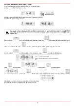
Page 91: ...levels By means of a proper use of the keys it is possible to enter the various level parameters as shown in the following flow chart The burner and consequently the LMV2x are factory set the air and...

Page 92: ...nd go back to the flashing number The Info level shows some basic parameters as 5 Example choose parameter 102 to show the date the display shows parameter 102 flashing on the left and characters _ _...

Page 93: ...h another message Diagnostic code in the example diagnostic code 3 Record the codes and find out the fault in the Error table To perform the reset press InFo for one second The unit displays an event...

Page 94: ...ht By pressinf or it is possible to scroll up down the parameter list 2 Once the last parameter is accessed 143 by pressing the End message will blink 3 Press InFo for more than three seconds or for m...

Page 95: ...ignition time OFF Ph44 t44 intervallo 1 t44 interval 1 Ph50 TSA2 secondo tempo sicurezza TSA2 2nd safety time Ph52 t52 intervallo 2 t52 interval 2 Ph60 Funzionamento 1 stazionario Operation 1 stationa...

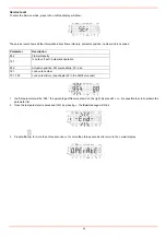
Page 96: ...ess ENTER until the display will show with the button go to the group 000 of the parameters and press with the buttons and go to 050 parameter press the disply show press again with the button select...

Page 97: ...uttons by pressing enter to confirm iWith the buttons go to the group 000 of the parameters press end select the 050 parameter press the disply show with the button the display shows press again with...

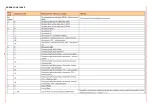
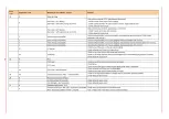
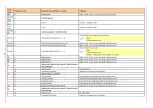
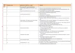
Page 98: ...50 ERROR CODE TABLE...

Page 99: ...51...

Page 100: ...52...

Page 101: ...53...

Page 102: ...54...

Page 103: ...55...

Page 104: ...56...

Page 105: ...57...

Page 106: ...58...

Page 107: ...59...

Page 108: ...60...

Page 109: ...61...

Page 110: ...62...

Page 111: ...63...

Page 112: ...64...

Page 113: ...L PE QRB C N ION QRB C X75 1 X10 05 1 X10 06 1 X3 02 1 PLUFT FLAMME P L PE N L 2 3 L X5 03 1 X8 04 1 X8 02 1 X5 03 X10 05 X7 01 X8 04 X8 02 X75 X10 06 X3 02 X3 04 N PE L 1 1 1 1 1 1 1 1 1 QRA QRA QRA...

Page 114: ...66 Wiring variants for LMV27 2 Fuel meter input 1 Supply fuel meter ConnectorX75 ConnectorX5 02 ConnectionsPmax...

Page 115: ...tion speed output 2 GND signal reference 1 Controller input 4 20mA 5 Supply 4 Feedback signal 3 PWM Pulse Width Modulation speed output 2 GND signal reference 1 External supply 24V DC ConnectorX75 Con...

Page 116: ...dulation speed output 2 GND signal reference 1 Controller input 4 20mA 5 Supply ConnectorX75 ConnectorX64 ConnectorX74 2 Fuel meter input 1 Supply fuel meter ConnectorX5 02 Connections Pmax 4 Feedback...

Page 117: ......

Page 118: ......

Page 119: ......

Page 120: ...and data subject to change Errors and omissions excepted C I B UNIGAS S p A Via L Galvani 9 35011 Campodarsego PD ITALY Tel 39 049 9200944 Fax 39 049 9200945 9201269 web site www cibunigas it e mail...

Reviews: