PART I: INSTALLATION
6
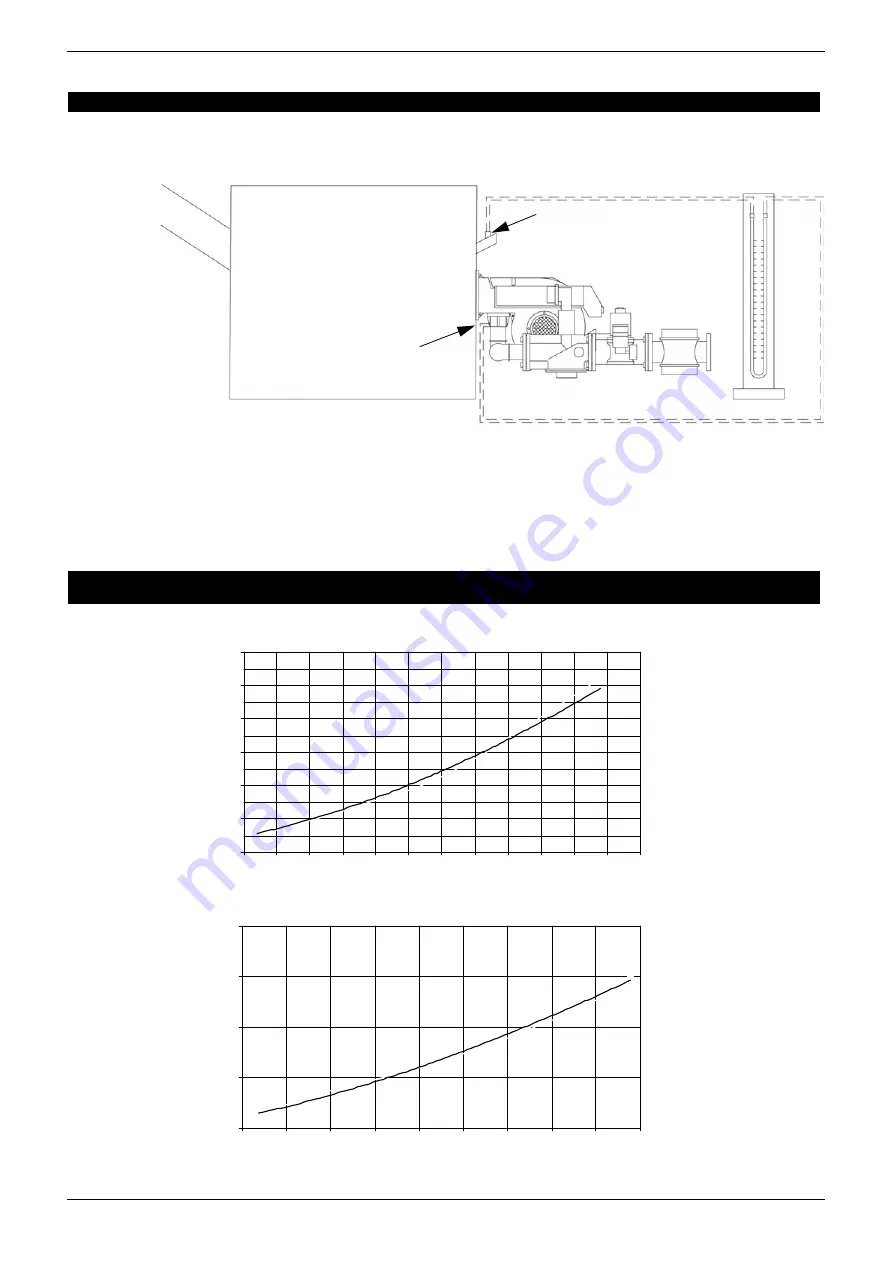
PRESSURE - RATE IN COMBUSTION HEAD CURVES
The pressure - gas rate curves are referred to the burner in operation with 3% of O
2
, with the combustion head at the maximum
opening, servocontrol at the maximum opening and gas butterfly valve fully opened.. Refer to Fig. 4, showing the correct way to
take the gas pressure, considering values of backpressure in combustion chamber.
Fig. 4
Key
1 Boiler
2 Gas pressure port on butterfly valve
3 Sightglass cooling port
4 Water column pressure gauge
Curves are referred to a null pressure in combustion head!
NOTE: THE PRESSURE-RATE CURVES ARE INDICATIVE; FOR A PROPER SETTING OF THE GAS RATE, PLEASE
REFER TO THE GAS METER READING.
G
AS PR
ESSU
R
E
IN
COM
B
US
T
ION HE
A
D
m
b
a
r
S10
NATURAL GAS FLOW RATE Stm
3
/h
Fig. 5
G
A
S
PR
ES
SU
R
E
I
N
C
O
MB
U
S
T
IO
N
H
E
A
D
mba
r
S18
NATURAL GAS FLOW RATE Stm
3
/h
Fig. 6
1
3
4
2
0
1
2
3
4
5
6
4
5
6
7
8
9
10
11
12
13
14
15
16
0
2
4
6
8
4
6
8
10
12
14
16
18
20
22
Summary of Contents for S10
Page 18: ...PART III MAINTENANCE 18 ELECTRICAL DIAGRAMS Electrical diagram 01 320 Rev 3...
Page 19: ...PART III MAINTENANCE 19 Electrical diagram 01 427...
Page 20: ...PART III MAINTENANCE 20 SPARE PARTS...
Page 29: ...APPENDIX COMPONENTS CHARACTERISTICS 29...
Page 30: ...APPENDIX COMPONENTS CHARACTERISTICS 30...
Page 31: ...APPENDIX COMPONENTS CHARACTERISTICS 31...
Page 32: ......


