CIB UNIGAS
- M039259CA
29
At least once a year carry out the maintenance operations listed below. In the case of seasonal servicing, it is recommended to carry
out the maintenance at the end of each heating season; in the case of continuous operation the maintenance is carried out every 6
months.
ROUTINE MAINTENANCE
Check and clean the oil filter cartdrige, replace if necessary.
Check and clean the filter inside the oil pump: filter must be thoroughly cleaned at least once in a season to ensure correct working
of the fuel unit. To remove the filter, unscrew the four screws on the cover. When reassemble, make sure that the filter is mounted
with the feet toward the pump body. If the gasket between cover and pump housing should be damaged, it must be replaced. An
external filter should always be installed in the suction line upstream of the fuel unit.
Check the fuel hoses for possible leaks.
Remove, clean and check the combustion head (see Fig. 14).
Check and clean the ignition electrodes, adjust and, if necessary, replace (Fig. 16).
Check and clean the detection photoresistor, adjust and, if necessary, replace it (Fig. 18).
Remove and clean the fuel nozzle
(Important:
cleaning must be performed using solvent, not metal tools!
).
At the end of
maintenance operations after the burner reassembly, light the flame and check its shape, replacing the nozzle whenever a questio-
nable flame shape appears. Whenever the burner is used intensely, we recommend preventively replacing the nozzle at the start of
each heating season.
Clean and grease levers and rotating parts.
IMPORTANT:Remove the combustion head before checking the ignition electrodes.
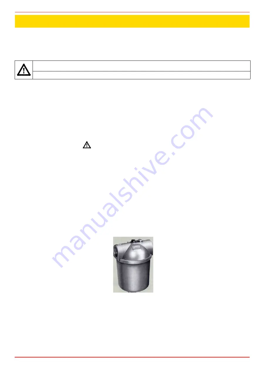
Oil filter maintenance
For correct and proper servicing, proceed as follows:
1
shut off fuel in the line section being serviced;
2
unscrew the tray;
3
remove the filter cartridge from its support and wash it with petrol or replace if necessary; check seal O-Ring, replace if necessary;
4
reassemble the tray and restore fuel flow.
WARNING: ALL OPERATIONS ON THE BURNER MUST BE CARRIED OUT WITH THE MAINS DISCONNECTED AND
THE FUEL MANAUL CUTOFF VALVES CLOSED!
ATTENTION: READ CAREFULLY THE “WARNINGS” CHAPTER AT THE BEGINNIG OF THIS MANUAL..
PART III: MAINTENANCE
Summary of Contents for TN90
Page 2: ......
Page 21: ...CIB UNIGAS M039259CA 21 Fig 9 Hydraulic diagram 3ID0014 Two or more burners configuration...
Page 34: ...CIB UNIGAS M039259CA 34...
Page 54: ......
Page 63: ......
Page 64: ......
Page 65: ...RWF50 2x RWF50 3x User manual M12922CB Rel 1 0 07 2012...
Page 80: ...16 Note Specifications and data subject to change Errors and omissions excepted...
Page 81: ...KM3 Modulator USER MANUAL M12927CA Rel 1 0 10 2020...
Page 82: ...M12927CA MOUNTING 2...
Page 106: ......
Page 107: ......
Page 108: ......
Page 109: ......
Page 110: ......
Page 111: ......
Page 112: ......


