CIB UNIGAS
- M039259CA
30
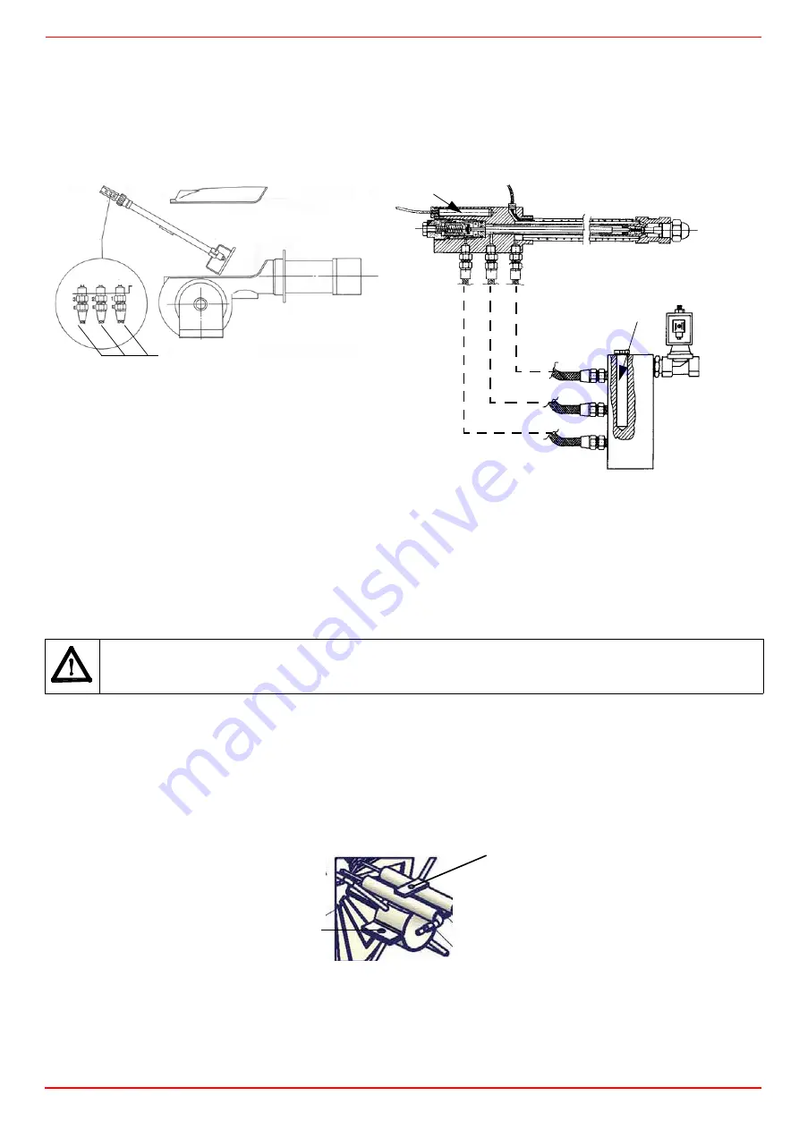
Removing the combustion head
Remove the cover H.
Slide the photoresistor out of its housing.
Unscrew the oil connections E (Fig. 14) connecting the flexible pipes to the gun L and remove the whole assembly as shown in Fig.
14-Fig. 15.
Removing the oil gun, replacing the nozzle and the electrodes
To remove the oil gun, proceed as follows:
1
remove the combustion head as described on the previous paragraph;
2
loosen the
VU
screw and remove the oil gun: check the oil gun, replace it fi necessary;
3
after removing the oil gun, unscrew the nozzle and replace it if necessary;
4
in order to replace the electrodes, unscrew the
VB
fixing screws and remove them: place the new electrodes being careful to
observe the measures shown on next paragraph: reassemlbe following the reversed procedure.
Caution
: adjust the nozzle position, by means of the
VU
screw.
Fig. 16
Fig. 14
Key
1 Inlet
2 Return
3 Gun opening
4 Heating wire (only on high density oil burners)
5 Cartdrige-type heater
H Cover
L Oil gun
E Oil piping connections
Fig. 15
ATTENTION:
avoid
the electrodes to get in touch with metallic parts (blast tube, head, etc.), otherwise the boiler operation
would be compromised. Check the electrodes position after any intervention on the combustion head.
H
E
1
2
3
L
1
2
3
3
2
1
5
4
5
VU
VB
Summary of Contents for TN90
Page 2: ......
Page 21: ...CIB UNIGAS M039259CA 21 Fig 9 Hydraulic diagram 3ID0014 Two or more burners configuration...
Page 34: ...CIB UNIGAS M039259CA 34...
Page 54: ......
Page 63: ......
Page 64: ......
Page 65: ...RWF50 2x RWF50 3x User manual M12922CB Rel 1 0 07 2012...
Page 80: ...16 Note Specifications and data subject to change Errors and omissions excepted...
Page 81: ...KM3 Modulator USER MANUAL M12927CA Rel 1 0 10 2020...
Page 82: ...M12927CA MOUNTING 2...
Page 106: ......
Page 107: ......
Page 108: ......
Page 109: ......
Page 110: ......
Page 111: ......
Page 112: ......


