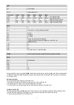
If t.oF = 0, current function is
maintained.
If t.oF ≠ 0 movement mode will be as
shown on the graph
t.Hi
t.on
t.on
t.on
t.oF
t.oF
t.oF
With the controller in manual, the setting of parameter At.y ≥ 8 allows direct control of the valve open and close commands through the keyboard Increments
and Decrements on the front seats.
V0 - for floating valve without potentiometer
Model V0 have similar behaviour: every manoeuvre request greater than the minimum impulse t.Lo is sent to the actuator by means of the OPEN/CLOSE
relays; every action updates the presumed position of the virtual potentiometer calculated on the basis of the actuator travel declared time.
In this way there is always a presumed position of the valve which is compared with the position request of the controller.
Having reached a presumed extreme position (entirely open or entirely closed determined by the “virtual potentiometer”) the controller provides a command in
the same direction, in this way ensuring the real extreme position is reached (minimum command time = t.on).
The actuators are usually protected against the OPEN command in the entirely open position or CLOSE command in the entirely closed position.
V3 - for floating valve, PI control
When the difference between the position calculated by the controller and the only proportional component exceeds the value corresponding to the minimum
impulse t.Lo the controller provides an OPEN or CLOSE command of the duration of the minimum impulse itself t.Lo.
At each delivery the integral component of the command is set to zero (discharge of the integral).
The frequency and duration of the impulses is correlated to the integral time (h.it or c.it).
Non-movement behavior
t.Hi = 0: with power = 100% or 0.0%, the corresponding open or close outputs always remain enabled (safety status).
Movement behavior
t.Hi < > 0: with position attained corresponding to 100% or 0.0%, the corresponding open or close outputs are switched off.
Valve control modes
Proportional Action:
action in which contribution to output is proportional to deviation at input (deviation = difference between controlled variable and setpoint).
Derivative Action:
action in which contribution to output is proportional to rate of variation input deviation.
Integral Action:
action in which contribution to output is proportional to integral of time of input deviation.
Influence of Proportional, Derivative and Integral actions on response of process under control
* An increase in P.B. reduces oscillations but increases deviation.
* A reduction in P.B. reduces the deviation but provokes oscillations of the controlled variable (the system tends to be unstable if P.B. value is too low).
* An increase in Derivative Action corresponds to an increase in Derivative Time, reduces deviation and prevents oscillation up to a critical value of
Derivative Time, beyond which deviation increases and prolonged oscillations occur.
* An increase in Integral Action corresponds to a reduction in Integral Time, and tends to eliminate deviation between the controlled variable and the
setpoint when the system is running at rated speed.
If the Integral Time value is too long (Weak integral action), deviation between the controlled variable and the setpoint may persist.
Contact GEFRAN for more information on control actions.
10 • CONTROL ACTIONS
11
80379_MHW_600V-T73_06-2012_ENG
Summary of Contents for TN90
Page 2: ......
Page 21: ...CIB UNIGAS M039259CA 21 Fig 9 Hydraulic diagram 3ID0014 Two or more burners configuration...
Page 34: ...CIB UNIGAS M039259CA 34...
Page 54: ......
Page 63: ......
Page 64: ......
Page 65: ...RWF50 2x RWF50 3x User manual M12922CB Rel 1 0 07 2012...
Page 80: ...16 Note Specifications and data subject to change Errors and omissions excepted...
Page 81: ...KM3 Modulator USER MANUAL M12927CA Rel 1 0 10 2020...
Page 82: ...M12927CA MOUNTING 2...
Page 106: ......
Page 107: ......
Page 108: ......
Page 109: ......
Page 110: ......
Page 111: ......
Page 112: ......


