5
Set up for pressure transmitter 2 wires signal 4÷20mA
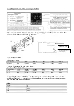
With pressure transmitters first we need to enable their power supply: remove the part as shown below, then,
on the CPU unit, move the bridge from Pt100 to +Vt
Verify wiring of the sensor
Impostazione set-point
Transmitter
1,6bar
3bar
10bar
16bar
25bar
40bar
Set-point 1bar
1,5bar
6bar 6bar 6bar 6bar
To modify it directly use "up" and "down" arrows.
By pushing
F
you go to parameter:
Transmitter
1,6bar
3bar
10bar
16bar
25bar
40bar
Hy.P 0,2bar
0,5bar
0,5bar 0,8bar 1,25bar 2bar
Hy.n
0bar
0bar
0bar
0bar
0bar
0bar
Keep pushing
F
until you see
PASS
, release
F
and through the arrows set
99
, push
F
and visualize
Pro
(protection code) default is
12
, through the arrows set
128
and push
F,
keep it pushed until all parameters
InF
,
CFG
,
InP
,
Out
,
PASS
are visualized.
CFG
S.tun 0
hPb
5
hIt 1,33
hdt
0,33
…
IN/OUT cards
Signal selection on
terminal 3
Summary of Contents for TN90
Page 2: ......
Page 21: ...CIB UNIGAS M039259CA 21 Fig 9 Hydraulic diagram 3ID0014 Two or more burners configuration...
Page 34: ...CIB UNIGAS M039259CA 34...
Page 54: ......
Page 63: ......
Page 64: ......
Page 65: ...RWF50 2x RWF50 3x User manual M12922CB Rel 1 0 07 2012...
Page 80: ...16 Note Specifications and data subject to change Errors and omissions excepted...
Page 81: ...KM3 Modulator USER MANUAL M12927CA Rel 1 0 10 2020...
Page 82: ...M12927CA MOUNTING 2...
Page 106: ......
Page 107: ......
Page 108: ......
Page 109: ......
Page 110: ......
Page 111: ......
Page 112: ......


