7
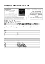
Set -up for thermocouples type
K
or
J
Verify wiring of the sensor
Regulation of the set-point =
80
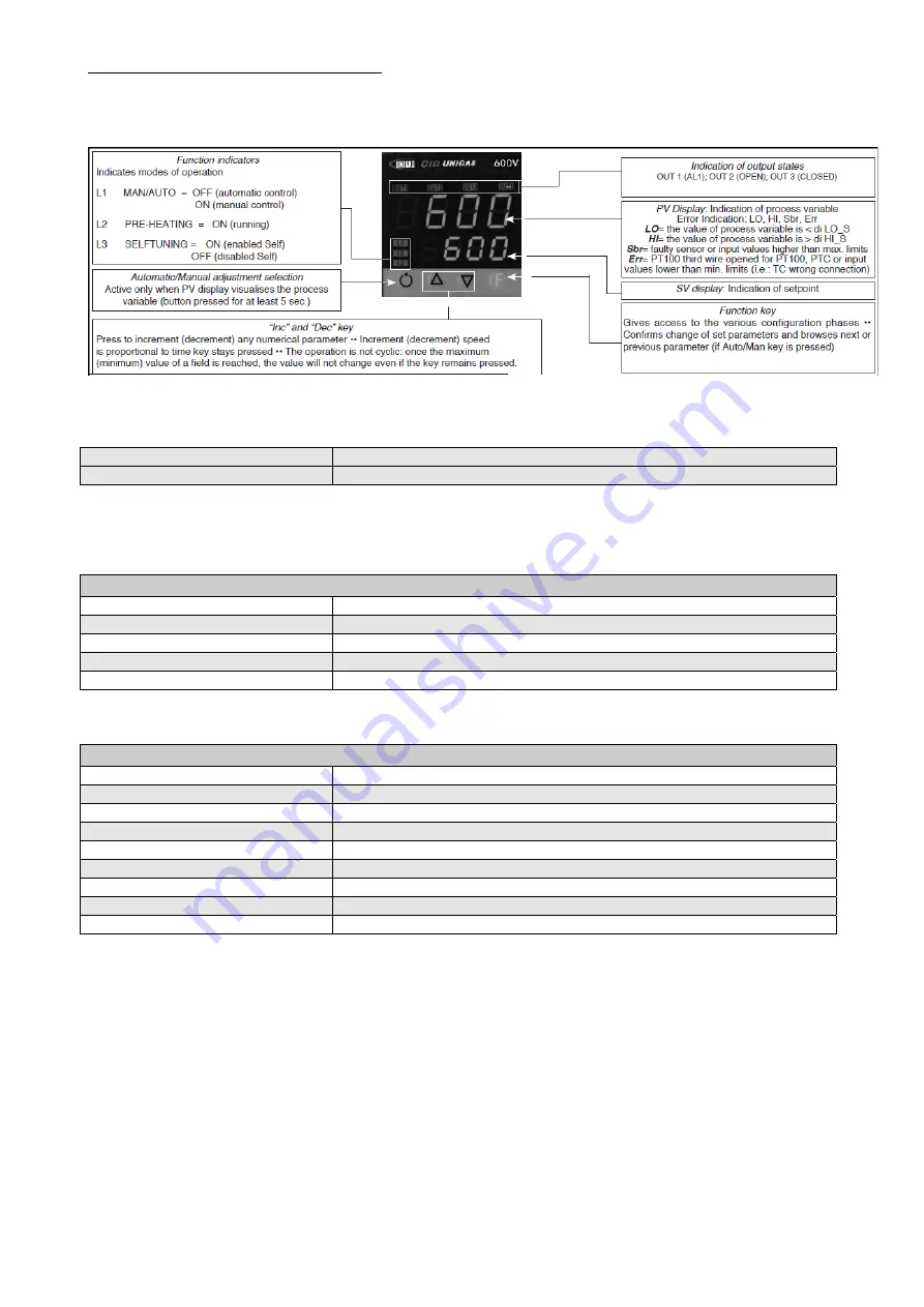
It can be modified by using arrows "up" and "down".
By pushing
F
you go to parameters:
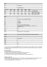
Hy.P
10 (hysteresis positive for output 1 terminals 21-22 (ex Q13-Q14)
Hy.n
-5 (hysteresis negative for output 1 terminals 21-22 (ex Q13-Q14)
Keep pushing
F
until you see
PASS
, release
F
and through the arrows set
99
, push
F
and visualize
Pro
(protection code) default is
12
, through the arrows set
128
and push
F,
keep it pushed until all parameters
InF
,
CFG
,
InP
,
Out
,
PASS
are visualized.
CFG
S.tun 0
hPb
1,2
hIt 5,83
hdt
1,33
…
InP
….
tyP
2 (thermocouple
K
0÷1300°C) / 0 (thermocouple
J
0÷1000°C)
…
dP_S
0 (no decimal) / 1 (1 decimal)
Lo.S
0 (min. sensor scale)
Hi.S
1300 (max sensor scale for tc
K
) / 1000 (max sensor scale for tc
J
)
oFS
0 (offset of input correction)
Lo.L
0 (lower set-point range limit)
Hi.L
1300 (upper set-point range limit) per tc
K
/ 1000 for tc
J
Summary of Contents for TN90
Page 2: ......
Page 21: ...CIB UNIGAS M039259CA 21 Fig 9 Hydraulic diagram 3ID0014 Two or more burners configuration...
Page 34: ...CIB UNIGAS M039259CA 34...
Page 54: ......
Page 63: ......
Page 64: ......
Page 65: ...RWF50 2x RWF50 3x User manual M12922CB Rel 1 0 07 2012...
Page 80: ...16 Note Specifications and data subject to change Errors and omissions excepted...
Page 81: ...KM3 Modulator USER MANUAL M12927CA Rel 1 0 10 2020...
Page 82: ...M12927CA MOUNTING 2...
Page 106: ......
Page 107: ......
Page 108: ......
Page 109: ......
Page 110: ......
Page 111: ......
Page 112: ......


