CIB UNIGAS - M039168CC
20
Electrical connections
To execute the electrical connections, proceed as follows:
1
remove the cover from the electrical board, unscrewing the fixing screws;
2
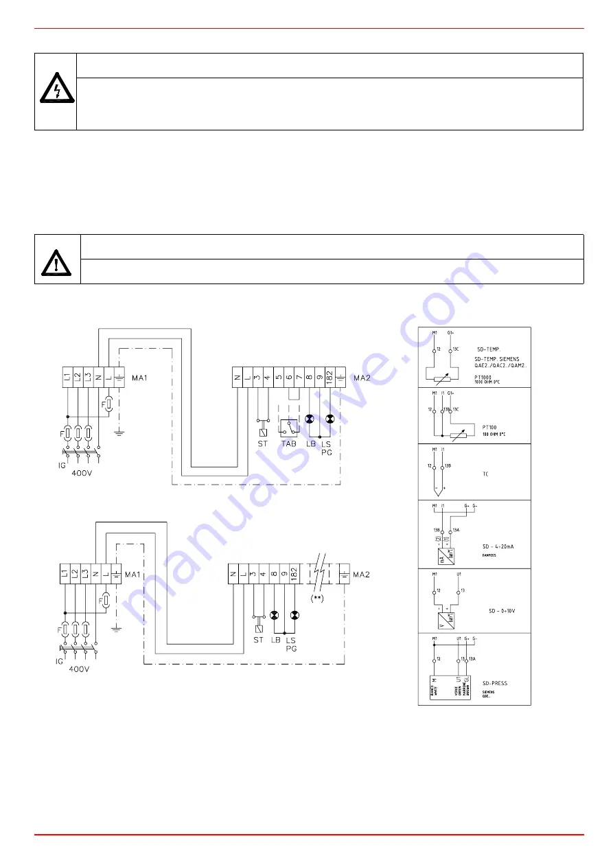
execute the electrical connections to the supply terminal board as shown in the following diagrams,
3
check the direction of the fan motor (see next pargraph)
4
refit the panel cover.
As for a complete decription of electrical diagrams, see page 39.
Rotation of fan motor
Once the electrical connection of the burner is executed, remember to check the rotation of the fan motor. The motor should rotate
according to the indication on the body. In the event of wrong rotation, reverse the three-phase supply and check again the rotation of
the motor.
Respect the basic safety rules. make sure of the connection to the earthing system. do not reverse the phase and
neutral connections. fit a differential thermal magnet switch adequate for connection to the mains.
ATTENTION: before executing the electrical connections, pay attention to turn the plant’s switch to OFF and be
sure that the burner’s main switch is in 0 position (OFF) too. Read carefully the chapter “WARNINGS”, and the
“Electrical connections” section.
WARNING: The burner is provided with an electrical bridge between terminals 6 and 7; when connecting the high/
low flame thermostat, remove this bridge before connecting the thermostat.
IMPORTANT: Connecting electrical supply wires to the burner teminal block MA, be sure that the ground wire is
longer than phase and neutral ones.
PROGRESSIVE BURNERS
FULLY MODULATING BURNERS
PROBE CONNECTION
Fig. 11


