background image

3 Negative (-data)

1

2

3

Male


XLR


Pin


Configuration:

US


ITT


Standard

OUTPUTS:

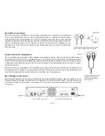
Binding Post/Banana Plug -

 Connect your speakers to the binding post outputs on the rear of the amplifier.  The 

speaker wire may be connect by bare wire (directly connected, usually for permanent connections), banana plug, 
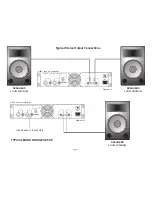
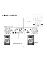
or spade connector. Connections are made to Channels 1 and 2 output’s for stereo mode or across the red termi-
nals of Channels 1 and 2 for Mono Bridge Mode. 

Important Notice:

 Although a speaker will operate with the positive and negative leads plugged into either termi-

nal on the amplifier  binding post, be sure to plug the negative lead into the black terminal and positive lead into 
the  red  terminal.  Ensuring  proper  polarity  will  avoid  speakers  being  out  of  phase,  that  can  cause  a  loss  of  bass 
response.

Important Notice: 

Banana Plugs - When connecting your speakers to the amplifier  using banana jacks; Be sure that the red and black 

caps on the binding post are completely screwed in. Insert the banana jacks into the caps of the binding post, be sure that the banana 
jack is inserted securely to avoid the risk of it popping out.

Set Up

INPUTS

 -   The   

A

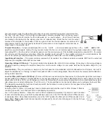
 series amplifiers allows you to use two types of input connectors per a channel, a XLR jack for balanced con-

nections and a 1/4” female jack that will accept balanced and unbalanced connectors. Use these connections to connect the output 
signal  from  a  mixer,  cross-over  or  EQ  to  your    

A

signal  from  a  mixer,  cross-over  or  EQ  to  your 

  series  amplifier. A  balanced  connection  is  recommended  for  cable  runs  longer 

that 20ft. When constructing your own XLR cables follow the pin configuration describe below for proper connections. For cable runs 
shorter than 20ft. you may choose the 1/4” unbalanced input option. The 1/4” unbalanced input option may be more convenient for 
most users due to the abundant supply of prefabricated cables available at your local audio dealer. You may use the two XLR “Input 
Thru” jacks to jump a parallel connection to another amplifier or other device. For Example: Connect a XLR cable to the input of chan-
nel one. You may now connect a XLR cable from the channel one “Input Thru” jack to the input jack of another amplifier’s channel one 
input. This will reduce the use of “Y” cables.

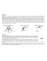
Diagram 7

Diagram 6

Diagram 5

Diagram 8

1 Ground / Return / 0v

2 Hot (+data)

Balanced TRS 1/4” Plug

Hot (+)

Negative (-)

Ground/Shield

Unbalanced TS 1/4” Plug

Hot (+)

Negative (-)

page 9

Summary of Contents for A-500

Page 1: ...PROTECT POWER PROFESSIONAL POWER AMPLIFIER LIMITER ON 0 10 POWER ON OFF LIMITER ON 0 10 SIGNAL 20dB 10dB CLIP PROTECT POWER PROFESSIONAL POWER AMPLIFIER LIMITER ON 0 10 POWER ON OFF 0 10 SIGNAL 20dB...

Page 2: ...le guide ATTENTION ATTENTION AVERTISSEMENT Este s mbolo tiene el prop sito de alertar al usuario de la presencia de voltaje peligroso que no tiene aislamiento dentro de la caja del producto que puede...

Page 3: ...00 7 A 1300 8 Inputs 9 Outputs 9 Operating Modes 13 Protection Circuitry Limiter 13 Short Circuit Protection 13 Thermal Protection 14 Low Cut Filter 14 Specifications 15 FOR OPTIMUM PERFORMANCE AND RE...

Page 4: ...qualified service personnel when The fixture should be serviced by qualified service personnel when A The power supply cord or the plug has been damaged A The power supply cor d or the plug has been d...

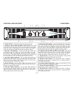
Page 5: ...Channel 2 Clip Indicator This red LED will begin to flash when channel two begins to overload clip At this point channel one will be gin to distort Under heavy clipping activity lower the channel one...

Page 6: ...hannel one speakers to channel one output 6 Circuit Breaker This breaker is designed to protect the amplifier and your speak ers in the event of an AC overload In the event of an electrical overload t...

Page 7: ...etails on input configuration 5 Mono Bridge Stereo Selectable Switch This switch changes the amplifier operating mode from either stereo or mono bridge Amplifiers are shipped in stereo mode 6 Fuse Hol...

Page 8: ...operating mode from either stereo or mono bridge Amplifiers are shipped in stereo mode 9 Fuse Holder This holder houses the external fuse Always replace with the exact same type fuse 10 Channel 2 XLR...

Page 9: ...of it popping out Set Up INPUTS The A series amplifiers allows you to use two types of input connectors per a channel a XLR jack for balanced con nections and a 1 4 female jack that will accept balan...

Page 10: ...ck caps on the binding post are tighten down completely Insert the banana jacks into the caps of the binding post be sure that the banana jack is inserted securely to avoid the risk of it popping out...

Page 11: ...IPMENT TO RAIN OF MOIS TURE AVIS RISQUE DE CHOC ELECT AVIS RISQUE DE CHOC ELECT TRIQUE NE PAS OUVRIR TRIQUE NE PAS OUVRIR P2 P3 P1 CH 1 CH 2 PROFESSIONAL POWER AMPLIFIER STEREO BRIDGE STEREO BRIDGE ST...

Page 12: ...4 Typical Stereo Set Up Typical Mixer A1300 series Rear View Typical Speaker Connect to Vplus series Channel One Output Typical Speaker Connect to Vplus series Channel Two Output Output Diagram 15 pa...

Page 13: ...s the gain of an overloading signal and reduces it the reduction in gain reduces distortion that can cause damage to your speakers and amplifier During normal operation below clipping and momentary cl...

Page 14: ...ure the source voltage for your areas matches the required voltage for your amplifier Gain Controls The gain controls are located on the front panel and are calibrated in 2dB of attenuation from full...

Page 15: ...power 8 ohms Input Sensitivity and Impedance rated output power 8 ohms 1 5v rms 1 1v RMS 0 dBv 1v RMS 0 dBv Dimensions Weight Height Width Depth Weight 3 5 8 8cm 19 48 3cm 15 9 40 7cm 26 4 lbs 12kg 3...

Reviews: