page 15
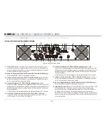
OPERATING VOLTAGE (AC MAINS) -
On the rear panel will indicate the correct AC mains voltage. Connecting to the wrong
voltage is dangerous and may damage the amplifier. Always be sure the source voltage for your areas matches the required voltage for your
amplifier.
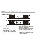
GAIN CONTROLS -
The gain controls are located on the front panel and are calibrated in 2dB of attenuation from full gain. It is best to
adjust the amplifier so no “hissing” is heard from speakers with no music being played, this will ensure the lowest possible distortion d u ring
normal operation.
CH. 1
CH.2
1
Low Cut
On / Off
2
ON=30Hz
OFF=50Hz
1 2
3 4
OFF
ON
3
ON=30Hz
OFF=50Hz
4
Low Cut
On / Off
UNiKA
DCA-900/DCA-1100/DCA-1300/DCA-2000
AMPLIFIER FEATURES
THRU (DCA-1100, DCA-1300 & DCA-2000) :
THRU will allow the user to daisy-chain one amplifier’s signal input into another amplifier. Plug the
signal source outputs into the first amplifier’s input, patch from the amplifier’s THRU jacks to the next amplifier’s input, and so on, daisy-chaining as many
amplifiers as there is no excessive level loss.
GROUND LIFT SWITCH :
Applying or lifting the ground switch will change level for background noise and hum, if the noise level remains the same in
either position, better to keep the ground lift switch in the ground position. This will eliminate 50Hz/60Hz cycle hum that is sometimes induced when
mounting several units in the same rack.
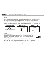
LOW CUT FILTER (DCA-1100 and DCA-1300 Only) -
The low-cut filter removes extremely low frequencies from the audio signal th
at could cause
speaker distortion or damage. The DIP switches on the rear panel allows you to enable or disable the filter for each channel, as well as adjust either a 50Hz
or 30 Hz cut-off. The DIP switches on the rear panel allow you to configure the low cut filter. The diagram below details the functions of each DIP switch, the
functions are also printed on the rear panel of the amplifier.
CONFIGURING THE LOW CUT FILTER:
ACTIVATING LOW CUT FILTERS -
DIP switches 1 and 4 activate and deactivate the Low Cut Filter. Channel 1 filters is controlled by DIP switch 1 and
channel 2 filter is controlled by DIP switch 4.
LOW CUT FREQUENCY SELECTOR -
When the Low Cut Filter is activated, DIP switches 2 (channel 1) and 3 (channel 2) will control the frequency roll-off.
When DIP switches 2 and 3 are in the "ON" position, the filter will cut off frequencies at and below 30Hz, when these DIP switches are in the "OFF" position,
the filter will cut off frequencies at and below 50Hz.
LED INDICATORS:
For the DCA series amplifiers, each channel has 4 LEDs. One red LED indicates signal clipping.
One red LED indicates protections mode for shorts/overload. One yellow LED indicates input signal is present. One yellow
LED indicates the mains power is activated. For the DCA-2000, except the two red LEDs as mentioned, each channel also
with four LEDs indicate signal level activity, and one red LED indicates overheating situation.
FUNCTION INDICATORS (DCA-2000 only):
These green/yellow/green LED indicators detail the amplifiers
current operating mode (Mono, Stereo or Bridge).
Introduction Front Panel Rear Panel Set Up Operating Modes
Specifications
Protection
Features


