12
DSP Audio Processor
The Camera icon will generate a .png picture file similar to a screen shot which you can save for
documentation or instruction purposes.
The
T
(text) icon will place the frequency, Q and gain values of each EQ and filter setting in the
graphical screen. These settings will anyway be visible when changes are being made, but with
the T icon activated, they will be visible continuously. This duplicates the numerical indications in
the lower part of the screen but it will be useful with the expanded screens mentioned before.
For very accurate settings of EQ or filtering you can click the Looking Glass icon. All movements of
the cursor now have a much smaller effect and you can drag curves with much greater precision,
clicking the Looking Glass again reverts to normal operation.
● 4.2.2 Input Gain, Mute
The right hand side of the screen shows the fader to set Input channel gain and a Mute button.
Settings are individual per channel unless input
channels have been linked in the Unit window.
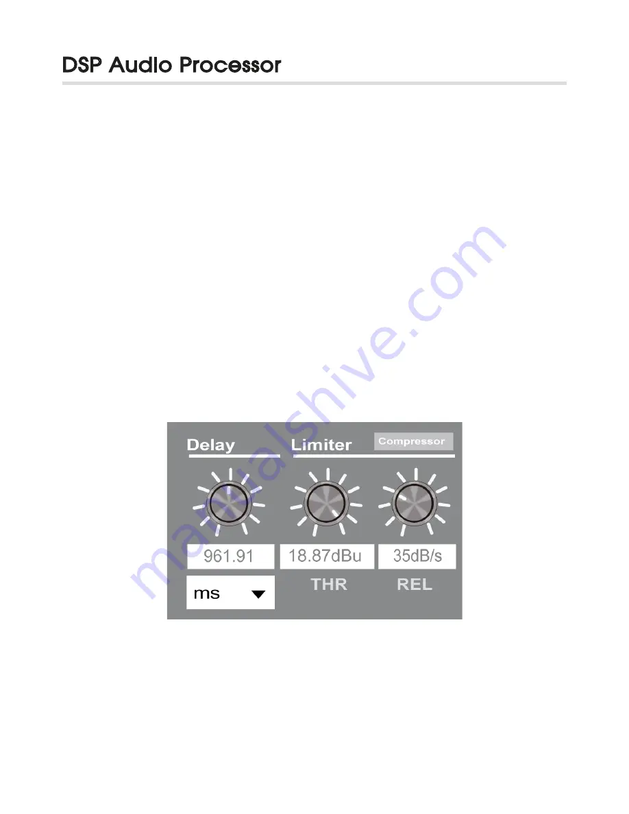
● 4.2.3 Delay, Limiter, Compressor
In the bottom right of the Input screen there are
settings for channel delay, limiter threshold
(-48 to +24 dBu) and Limiter release rate (10 to 100 dB/s) settings plus a button to enter the
RMS Compressor menus. Channel delay can be set in a variety of distance or time units from
the drop-down list.
Figure 13: Detail of Delay, Limiter & Compressor in input- window


