background image

PARALLEL

STEREO

BRIDGE

SUB

WOOF

NORMAL

FREQUENCY

NORMAL

SUB

WOOF

FREQUENCY

20 Hz

20 Hz

200 Hz

200 Hz

INPUT BALANCE

INPUT THRU

PUSH TO RESET

BRIDGE

MONO

_

+                   

+                   

+                   

_

CH-1

CH-2

CH-2

CH-1

_

OUTPUTS

PINOUT

1+

1-

POS NEG

CH- 2

PINOUT

2+

2-

POS NEG

CH- 2

1+

2+

POS NEG

BRIDGE

1+

1-

POS NEG

CH- 1

CH-1

CH-2

CH-1

CH-2

GAIN

0.775V

26dB

32dB

Made in Taiwan

SUBWOOFER MODE ( GX-4000 / GX-5000 / GX-7000 only ) : 

This mode sends low frequencies to your speakers without the use of an external cross-

over. The subwoofer operation can be operated in stereo, parallel, or bridge mono modes. Change the different operating modes by flipping the mode switch on the rear 
of the unit to your desired operating mode. Also, set the subwoofer mode switch to the “SUBWOOF” position. Use the frequency selector to adjust the subwoofer output 
frequency from 20Hz to 200Hz. The different subwoofer modes are listed as follows:

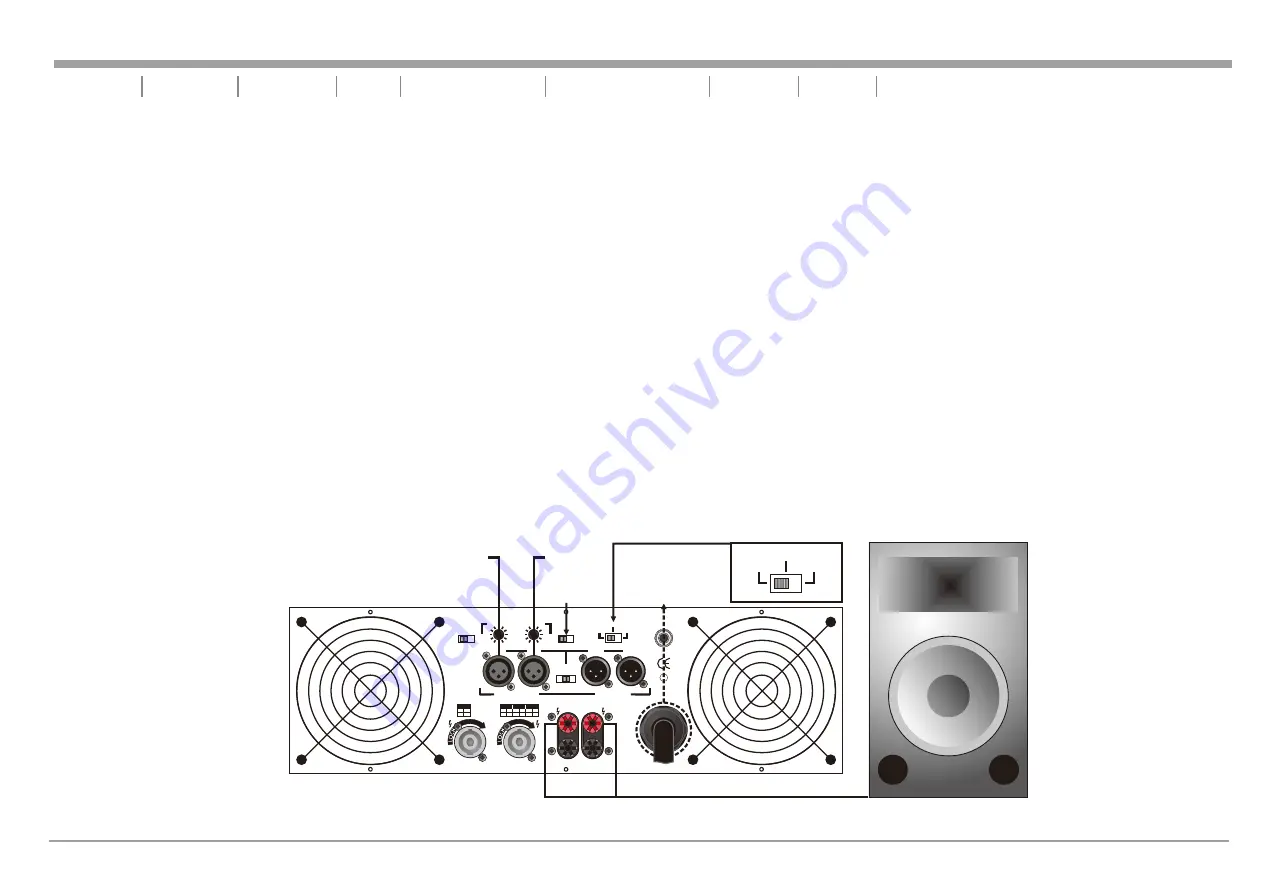
BRIDGE SUBWOOFER - 

This operation allows you to get the most possible power out of your amplifier for the sole purpose of running a high powered subwoofer 

loudspeaker in mono. To avoid amplifier overheating, never run the amplifier below 4 ohms in this mode. In this mode you may use the frequency adjustment on the rear 
of the amplifier, to control the frequency output level. Frequencies may be adjusted from 20Hz to 200Hz. Page 1  / 

 19 details a typical Bridge Subwoofer set-up.

3 Figure

STEREO SUBWOOFER - 

This operation is similar to the Bridge Subwoofer operation but in stereo. This operation allows you to run several subwoofers down to a 

minimum of 2 ohms. To avoid amplifier overheating, never run the amplifier below 2 ohms in this mode. Set up this mode as you would a standard Stereo set-up. Be sure 
both channels are set to “SUBWOOF.” In this mode you may use the frequency adjustment on the rear of the amplifier, to control the bass frequency output level. 
Frequencies may be adjusted from 20Hz to 200Hz. Page 1  / 

 20 details a typical Stereo Subwoofer set up.

4 Figure

PARALLEL SUBWOOFER - 

This operation is similar to the Stereo Subwoofer operation but in Parallel. When running subwoofers, it is usually recommended to run 

them in mono mode to achieve a cleaner tighter low end. This operation allows you to run several subwoofers down to a minimum of 2 ohms. To avoid amplifier 
overheating, never run the amplifier below 2 ohms in this mode. Set up this mode as you would a standard Stereo set-up. Be sure both channels are set to “SUBWOOF” 
and the mode switch is set to “Parallel.” In this mode you may use the frequency adjustment on the rear of the amplifier, to control the bass frequency output level. 
Frequencies may be adjusted from 20Hz to 200Hz.

ONE CHANNEL NORMAL / ONE CHANNEL SUBWOOFER (BI-AMP) -

You may also use your amplifier to bi-amp your system. You may use one side of the amplifier 


to power a subwoofer and the other side to power a full range speaker. Follow the set up guides listed above to mix and match your operations.

page 13

Do Not Use 
CH-2 Input

CH-1 Input

Set to
Subwoof

Negative (-) Lead

Positive (+) Lead

GX-7000 
Rear Panel

Bridge Subwoofer Mode Speaker Set-Up

Figure 19

Use the two red terminal from the Binding Post to 
power a subwoofer speaker in mono-bridge mode. 

Introduction      Front Panel      Rear Panels      Set Up      Speakon Assembly      

      Protection      Features      Specifications

Operating Modes

UNiKA

 GX-3000/GX-4000/GX-5000/GX-7000

GX-7000
only(110V)

Made in Taiwan

~120VAC  60Hz

5600 WATTS

PARALLEL

STEREO

BRIDGE

Summary of Contents for GX-3000

Page 1: ... 1 CH 2 0 10 0 10 POWER ON OFF PROFESSIONAL POWER AMPLIFIER UNiKA PROFESSIONAL PRODUCTS GX 4000 LIMITER ON LIMITER ON 20dB SIGNAL 10dB CLIP PROT CH 1 CH 2 0 10 0 10 ON OFF PROT CLIP 10dB 20dB SIGNAL PARALLEL STEREO BRIDGE GX 3000 UNiKA PROFESSIONAL PRODUCTS PARALLEL STEREO BRIDGE LIMITER ON LIMITER ON 20dB SIGNAL 10dB 5dB CLIP PROTECT PROTECT CLIP 5dB 10dB 20dB SIGNAL CH 1 CH 2 0 10 0 10 POWER ON ...

Page 2: ...ateur lisez les avertissements supplémentaries situés dans le guide Ce symbole est utilisé pour indiquer à l utilisateur qu il trouvera d importantes instructions importantes sur l utilisation et l entretien de l appareil dans la littérature accompagnant le produit Dieses Symobl soll den Anwender vor unisollierten gefährlichen Spannungen innerhalb des Gehäuses warnen die von Ausreichender Stärke s...

Page 3: ...amaged B Objects have fallen or liquid has been spilled into the unit C The appliance has been exposed to rain or water D The fixture does not appear to operate normally or exhibits a marked change in performance Congratulations and thank you for purchasing GX 3000 GX 4000 GX 5000 GX 7000 amplifier These amplifiers are representation of UNiKA s continuing commitment to produce the best and highest...

Page 4: ... This is to protect any speakers connected to the channel 6 Channel 1 Limiter Switch This is used to activate the channel s built in limiter The limiter reduces the average input level when the signal begins to distort this process is designed to reduce distortion and protect the speakers See limiter at page 15 7 Function Indicators These indicators detail the operating mode of the amplifier These...

Page 5: ...y glow when the unit has been turned off this is normal 11 Channel 2 Signal Indicators These green and yellow LEDs will glow according to the average signal output 12 Fan Inlet Grills and Filter GX Series amplifiers are cooled by two rear mounted fans Cool air from front grills is filtered and flows over the heatsinks and exhausts to back side Make sure these outlets remain clear to allow unrestri...

Page 6: ...en using your amplifier in subwoofer mode 20 Channel 1 Frequency Adj This pot adjust the frequency level sent to your speaker on channel one when using your amplifier in subwoofer mode 21 Channel 1 XLR Input Connector This is the input terminal of the audio signal that can be connected to the balanced XLR input connector XLR pin setting Pin 2 signal positive Pin 3 signal negative Pin 1 ground 22 C...

Page 7: ... Channel 1 Speakon Output Use pins 1 and 1 of this 4 pole Speakon connector to connect to your speaker s Speakon input jack 30 Input Gain This sensitivity selector sets the input level for rated power output 0 775V 1V 1 44V GX 3000 and 0 775V 26dB 32dB GX 4000 5000 7000 31 Channel 2 Output Jack 5 way Binding Post Connect to your speakers input jack Red is positive signal and Black is negative sign...

Page 8: ... permanent connections banana plug or spade connector Connections are made to channel one and channel two outputs for Stereo Mode or across the red terminals of channel one and channel two for Mono Bridge Mode IMPORTANT NOTICE Although a speaker will operate with the positive and negative leads plugged into either terminal on the amplifier binding post be sure to plug the negative lead into the bl...

Page 9: ...e wire into the binding post and tighten Typical speaker output using spade connectors Insert bare wire into the binding post and tighten Figure 8 STEREO CONNECTIONS USING THE NEUTRIK SPEAKON OUTPUT CONNECTORS Recent regulatory requirements in Europe have outlawed the use of the dual banana plug and force amp users to terminate their speaker cables with spade lugs or bare wire ends This is not adv...

Page 10: ... housing A making sure that the large notch on the outer edge of the insert lines up with the large groove on the inside of the connector housing The insert should slide easily through the housing and out the other side until it extends approximately 3 4 inch from the end of the housing 6 Slide the cable tensioner D along the cable and insert into the housing A making sure that the large notch lin...

Page 11: ... signal without the need for external jumpers or wiring Both amplifier channels will operate independently Though they carry the same signal their gain controls affect only their respective channels and they both must use their respected speaker outputs Never attempt to parallel the speaker outputs this may cause serious damage to your amplifier This mode is recommended when using the GX 3000 GX 4...

Page 12: ... Modes UNiKA GX 3000 GX 4000 GX 5000 GX 7000 SPEAKERS 4 OHM MINIMUM CH 1 Input GX 7000 Rear Panel Only Figure 17 TYPICAL MONO BRIDGE SET UP Figure 16 TYPICAL MONO BRIDGE SET UP SPEAKERS 4 OHM MINIMUM Made in Taiwan PUSH TO RESET CH 2 CH 1 THRU THRU INPUT INPUT CAUTION MINIMUM LOAD IMPEDANCE 2 OHM PER CHANNEL 4 OHM BRIDGE Serial No H 2 C 1 1 POS NEG CH 2 1 1 POS NEG BRIDGE H 1 C K C O L K C O L K C...

Page 13: ...RS 2 OHM MINIMUM CH 1 Input CH 2 Input PARALLEL STEREO BRIDGE SUB WOOF NORMAL FREQUENCY NORMAL SUB WOOF FREQUENCY 20 Hz 20 Hz 200 Hz 200 Hz INPUT BALANCE INPUT THRU PUSH TO RESET BRIDGE MONO _ _ CH 1 CH 2 CH 2 CH 1 _ OUTPUTS PINOUT 1 1 POS NEG CH 2 PINOUT 2 2 POS NEG CH 2 1 2 POS NEG BRIDGE 1 1 POS NEG CH 1 CH 1 CH 2 CH 1 CH 2 GAIN 0 775V 26dB 32dB Made in Taiwan GX 7000 Rear Panel PARALLEL STEREO...

Page 14: ...2 ohms in this mode Set up this mode as you would a standard Stereo set up Be sure both channels are set to SUBWOOF In this mode you may use the frequency adjustment on the rear of the amplifier to control the bass frequency output level Frequencies may be adjusted from 20Hz to 200Hz Page 1 20 details a typical Stereo Subwoofer set up 4 Figure PARALLEL SUBWOOFER This operation is similar to the St...

Page 15: ...RMAL FREQUENCY NORMAL SUB WOOF FREQUENCY 20 Hz 20 Hz 200 Hz 200 Hz INPUT BALANCE INPUT THRU PUSH TO RESET BRIDGE MONO _ _ CH 1 CH 2 CH 2 CH 1 _ OUTPUTS PINOUT 1 1 POS NEG CH 2 PINOUT 2 2 POS NEG CH 2 1 2 POS NEG BRIDGE 1 1 POS NEG CH 1 CH 1 CH 2 CH 1 CH 2 GAIN 0 775V 26dB 32dB Made in Taiwan GX 7000 Rear Panel GX 7000 only 110V Made in Taiwan 120VAC 60Hz 5600 WATTS PARALLEL STEREO BRIDGE SUB WOOF ...

Page 16: ... minimum An amplifier s peak current draw at full output power into 2 ohms is several times what the normal draw is but its various protection circuits will prevent this condition lasting more than a minute or two page 15 SHORT CIRCUIT PROTECTION The GX Series amplifiers comes with built in Output Short Circuit Protects The Output Short Circuit Protection protects the output devices of the amplifi...

Page 17: ...ground switch will change level for background noise and hum if the noise level remains the same in either position better to keep the ground lift switch in the ground position This will eliminate 50Hz 60Hz cycle hum that is sometimes induced when mounting several units in the same rack LED INDICATORS Each channel has six LEDS for the GX 3000 only has five LEDs Four LEDs indicate signal level acti...

Page 18: ...00 GX 5000 GX 7000 GX 3000 2000W 1400W 2ohms 1000W 4ohms 700W 8ohms 420W 1 44V 1V 0 775V 0 2dB 0 01 70dB 360 990W 9A 110V CLASS AB Dual 2 speed fans and heatsinks 88 x 483 x 410 mm 17kg 2U 100dB 2400W 2000W 2ohms 1200W 4ohms 1000W 8ohms 620W 26dB 32dB 0 775V 0 2dB 0 025 70dB 600 1380W 12 54A 110V CLASS AB Dual 2 speed fans and heatsinks 133 x 483 x 410 mm 25 3kg 3U 100dB GX 4000 3200W 2800W 2ohms ...

Page 19: ...page 18 UNiKA GX 3000 GX 4000 GX 5000 GX 7000 ...

Page 20: ...Professional Power Amplifiers UNiKA ...

Reviews: