background image

0dB

-

2

5

9

13

18

22

26

32

46

8

0dB

-

2

5

9

13

18

22

26

32

46

8

0dB

-

2

5

9

13

18

22

26

32

46

8

0dB

-

2

5

9

13

18

22

26

32

46

8

CHANNEL 1

CHANNEL 3

CHANNEL 2

CHANNEL 4

PROTECT

PROTECT

CLIP

CLIP

CLIP

CLIP

SIGNAL

SIGNAL

SIGNAL

SIGNAL

UNiK A

PROFESSIONAL STEREO AMPLIFIER

MT-

600 Q

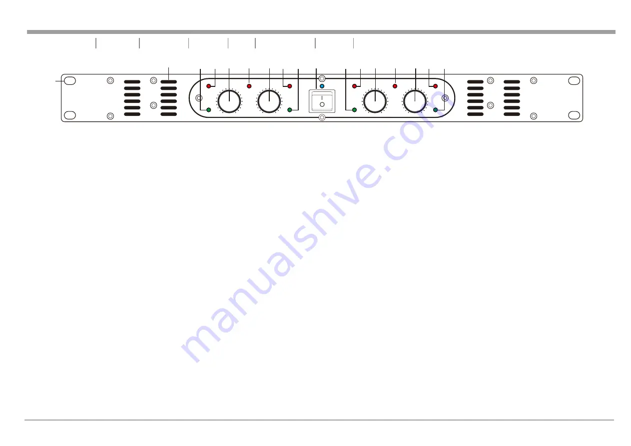
MT-600Q FRONT PANEL

1. Standard 19" rack mounting holes are provided on the front panel.

2. Cooling Vent - 

These vents are used for proper cooling. Never block these vents 

when installing the amplifier or other associated equipment and keep them clean 
at all time. Air must flow unimpeded through these ports.

3. Channel 1 Signal Indicator - 

This green LED will glow when there is audio signal 

connected to channel one’s input connector.

4. Channel 1 Clip Indicator - 

The red clip LED will begin to flash when the channel 

begins to overload. At this point the channel output signal will begin to distort. 
Under heavy clipping activity, lower the channel's gain control to reduce the risk of 
damage to your speakers and amplifier. This LED may glow when the unit has 
been turned off, this is normal.

5. Channel 1 Gain Control - 

This rotary knob is used to control the output signal 

level of channel one. Tuning the knob in clockwise direction will increase signal 
output level.

6. Channel 1 &2 Protect Indicator - 

The red protect LED will begin to glow when 

any one of the channels (CH-1/CH-2) goes into protect mode. When one of the 
channels goes into protect mode, all outputs for the two channels will turn off. This 
is to protect any speakers connected to the channels. 

7. Channel 2 Gain Control - 

This rotary knob is used to control the output signal 

level of channel two. Tuning the knob in clockwise direction will increase signal 
output level.

8. Channel 2 Clip Indicator - 

The red clip LED will begin to flash when the channel 

begins to overload. At this point the channel output signal will begin to distort. 
Under heavy clipping activity, lower the channel's gain control to reduce the risk of 
damage to your speakers and amplifier. This LED may glow when the unit has 
been turned off, this is normal.

9. Channel 2 Signal Indicator - 

This green LED will glow when there is audio signal 

connected to channel two’s input connector.

10. AC Power Switch - 

MT-600Q power amplifier has a front-panel AC mains 

power switch.

11. Channel 3 Signal Indicator - 

This green LED will glow when there is audio 

signal connected to channel three’s input connector.

12. Channel 3 Clip Indicator - 

The red clip LED will begin to flash when the 

channel begins to overload. At this point the channel output signal will begin to 
distort. Under heavy clipping activity, lower the channel's gain control to reduce 
the risk of damage to your speakers and amplifier. This LED may glow when 
the unit has been turned off, this is normal.

13. Channel 3 Gain Control - 

This rotary knob is used to control the output signal 

level of channel three. Tuning the knob in clockwise direction will increase 
signal output level.

14. Channel 3 & 4 Protect Indicator - 

The red protect LED will begin to glow 

when any one of the channels (CH-3/CH-4) goes into protect mode. When one 
of the channels goes into protect mode, all outputs for the two channels will 
turn off. This is to protect any speakers connected to the channels. 

15. Channel 4 Gain Control - 

This rotary knob is used to control the output signal 

level of channel four. Tuning the knob in clockwise direction will increase signal 
output level.

16. Channel 4 Clip Indicator - 

The red clip LED will begin to flash when the 

channel begins to overload. At this point the channel output signal will begin to 
distort. Under heavy clipping activity, lower the channel's gain control to reduce 
the risk of damage to your speakers and amplifier. This LED may glow when 
the unit has been turned off, this is normal.

17. Channel 4 Signal Indicator - 

This green LED will glow when there is audio 

signal connected to channel four’s input connector.

page 3

Figure


1

Important Precautions     Introduction

     Rear Panel     Set Up     Operating Modes     Protection     Specifications


Front Panel

1

2

3

4

5

7

6

UNiKA

 MT-600Q

8

9

10

11

12 13

15

14

16

17

Summary of Contents for MT Series

Page 1: ...tion 02 03 Front Panel 04 Rear Panel 05 Set Up 07 Operating Modes 08 Protection 09 Specifications 0dB 2 5 9 13 18 22 26 32 46 8 0dB 2 5 9 13 18 22 26 32 46 8 0dB 2 5 9 13 18 22 26 32 46 8 0dB 2 5 9 13 18 22 26 32 46 8 CHANNEL 1 CHANNEL 3 CHANNEL 2 CHANNEL 4 PROTECT PROTECT CLIP CLIP CLIP CLIP SIGNAL SIGNAL SIGNAL SIGNAL UNiKA PROFESSIONAL STEREO AMPLIFIER MT 600Q P R O F E S S I O N A L A U D I O ...

Page 2: ...ements supplémentaries situés dans le guide Ce symbole est utilisé pour indiquer à l utilisateur qu il trouvera d importantes instructions importantes sur l utilisation et l entretien de l appareil dans la littérature accompagnant le produit Dieses Symobl soll den Anwender vor unisollierten gefährlichen Spannungen innerhalb des Gehäuses warnen die von Ausreichender Stärke sind um einen elektrische...

Page 3: ...he power supply cord or the plug has been damaged B Objects have fallen or liquid has been spilled into the unit C The appliance has been exposed to rain or water D The fixture does not appear to operate normally or exhibits a marked change in performance Congratulations and thank you for purchasing MT 600Q amplifier This amplifier is representation of UNiKA s continuing commitment to produce the ...

Page 4: ...reduce the risk of damage to your speakers and amplifier This LED may glow when the unit has been turned off this is normal 9 Channel 2 Signal Indicator This green LED will glow when there is audio signal connected to channel two s input connector 10 AC Power Switch MT 600Q power amplifier has a front panel AC mains power switch 11 Channel 3 Signal Indicator This green LED will glow when there is ...

Page 5: ...lows the amplifier operating mode from either stereo or mono bridge selection Amplifiers are factory configured for Stereo Mode See section on Mode Selection for more information 21 AC Power Input IEC AC power inlet connector plug this cable in to a standard 110Vac or 220Vac wall outlet Be sure that supplied voltage matches that of the required voltage of your amplifier Never plug your amplifier i...

Page 6: ...s are made to channel one and channel two outputs for Stereo Mode or across the red terminals of channel one and channel two for Mono Bridge Mode please follow the same connections aforementioned on the channel three and channel four for Stereo Mode or Mono Bridge Mode IMPORTANT NOTICE Although a speaker will operate with the positive and negative leads plugged into either terminal on the amplifie...

Page 7: ... CONNECTOR Figure 7 When connecting your speakers to the amplifier using spade connector unscrew the red and black caps on the binding post be sure not to completely remove or unscrew the red and black caps Insert the spade connector into the binding post and tighten the caps down on the spade connector To reduce the risk of shock or damage to your amplifier be sure that the wire connected to one ...

Page 8: ...m Bridge Mode 120VAC 60Hz 1200VA FUSE T250V 10A L CAUTION REPLACE WITH SAME TYPE FUSE AND RATING ATTENTION RISQUE DE CHOC ELECTRIQUE NE PAS OUVRIR WARNING TO REDUCE THE RISK OF FIRE OR ELECTRIC SHOCK DO NOT EXPOSE TO RAIN OR MOISTURE CAUTION RISK OF ELECTRIC SHOCK DO NOT OPEN Designed and developed in the USA Manufactured in Taiwan Figure 9 Typical Stereo Output Connections MT 600Q REAR PANEL CH 1...

Page 9: ...ly event the heatsinks should reach 194 degrees Fahrenheit the amplifier will mute until it cools down enough for safe operation Make sure there is adequate ventilation around the heatsinks if you plan on rack mounting the MT 600Q in an enclosed space 3 The MT 600Q is fully protected from shorts opens over current and over voltage A relay disconnects the outputs under any of these fault conditions...

Page 10: ...ower Requirements 1 75 H x 19 0 W x 13 5 D 44 5mm x 482 6mm x 190 5mm 19 8 lbs 9 0kg TRS balanced unbalanced Euroblock balanced unbalanced Multi Way Binding Post 44k ohms balanced 22k ohms unbalanced 1V for full power output into 8 ohms 4 x 100Watts Channel RMS 4 x 140Watts Channel RMS 2 x 200Watts Channel RMS 2 x 280Watts Channel RMS 2 ohms stereo short term 4 ohms bridge short term 60dB typical ...

Page 11: ...page 10 Important Precautions Introduction Front Panel Rear Panel Set Up Operating Modes Protection Specifications UNiKA MT 600Q ...

Page 12: ...P R O F E S S I O N A L A U D I O ...

Reviews: