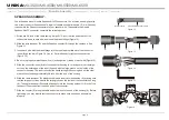

PROTECTION
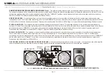
LIMITER -
The
MX-3500/
MX-4500/MX-5500/MX-6500 amplifiers comes with a built in limiter. When the input signal overloads, the “CLIP LED” indicates a signal
overload, at this time, the volume should be lowered to reduce distortion. If the input gain level is not reduced the built-in limiter will activate. During signal overload, the
limiter will reduce the input audio signal enough to minimize the amount of clipping. A limiter takes the gain of an overloading signal and reduces it, the reduction in gain
reduces distortion that can cause damage to your speakers and amplifier. During normal operation below clipping, and momentary clips on peaks, the limiter does not
affect the audio signal and is inaudible. It will allow brief clipping of peaks and will only activate when continuous hard clipping occurs. During excessive clipping the
limiter will reduce the audio signal enough to minimize the amount of clipping. When the input signal decreases enough that clipping ends, the limiter will deactivate and
cease its gain reduction. The limiter has a fixed threshold and can not be adjusted.
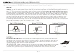
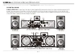
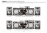
SAFE POWER LEVELS AT DIFFERENT OUTPUT LOADS:
8-Ohm Loads :
The amplifier can operate at its rated power level without risk of overheating. However, it may caused excessive temperature if it is pushed hard enough
to continually light the “CLIP” indicator, the amplifier’s average output power can reach its maximum peak.
4-Ohm Loads :
If the “CLIP” indicator flashes occasionally, the amplifier is approaching its Maximum long-term power capacity. If it is lit about half the time, the amplifier
channel will probably go into thermal protection within a few minutes.
2-Ohm Loads :
Except for an occasional flash, keep the “CLIP” indicator dark to avoid overheating the amplifier channel. Clipping should be kept to a reasonable
minimum. An amplifier’s peak current draw at full output power into 2 ohms is several times what the “normal ” draw is, but its various protection circuits will prevent this
condition lasting more than a minute or two.
page 14
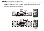
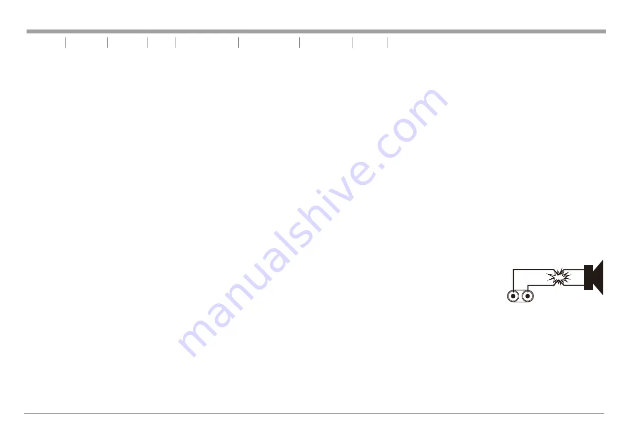
SHORT CIRCUIT PROTECTION -
The
MX-3500/
MX-4500/MX-5500/MX-6500 amplifiers comes with built-in Output Short Circuit
Protects. The Output Short Circuit Protection protects the output devices of the amplifier from short circuits and stressful loads. If your
speaker lines shorted, the amplifier automatically detects this problem and discontinued operation for that channel. If one side of your
amplifier becomes shorted and goes into protect mode, the other side will continue to operate normally. Channel output during the
“Short Circuit Protection" will be interrupted (i.e. no sound output). Short Circuit Protection can usually be traced back to the signal
output line (i.e. speaker line). Check the line from the output terminal of the amplifier to the speaker. If this line is good, check the
internal speaker connections and components. A short circuit will usually be traced to a bad cable or a bad speaker component and is
rarely traced to the amplifier itself.
Introduction Front Panel Rear Panel Set Up Speakon Assembly Operating Modes
Features Specifications
Protection
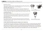
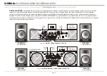
THERMAL PROTECTION -
Dual 2 speed fans on the
MX-3500/
MX-4500/MX-5500/MX-6500 amplifiers provide adequate cooling. During low level output
the fans run at normal speeds. During high output and as heat raises, (exceeding 50°C.), the fans will run at higher speeds to aid the cooling process. If the
heatsink temperature exceeds 91°C., the amplifier will mute until the amplifier cools down. When the amplifier cools below 90°C., the amplifier will return to
normal operations. Be sure not to operate your amplifier below the minimum load ratings to reduce the risk of overheating problems.
UNiKA
MX-3500/MX-4500/MX-5500/MX-6500


