background image

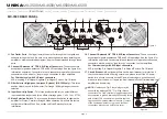
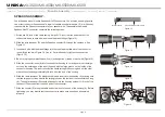
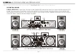
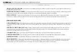
BANANA PLUG: (Figure 9) 

When connecting your speakers to the amplifier using banana plug, be sure that the red and black caps on 
the binding post are completely screwed in. Insert the banana plug into the caps of the binding post, be sure 
that the banana plug is inserted securely to avoid the risk of popping out.

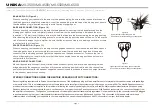
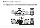
BARE WIRE CONNECTION: (Figure 10)

When connecting your speakers to the amplifier using bare wire, unscrew the red and black caps on the 
binding post, be sure not to completely remove or unscrew the red and black caps. Strip back the wire 
insulation ½” (13mm). Insert the bare wire into the hole that was reveled by unscrewing the binding post cap. 
After inserting the wire into the binding post hole, screw the binding post cap down on the wire. To reduce the 
risk of shock or damage to your amplifier, be sure that the wire connected to one binding post does not come 
in contact with that of another.

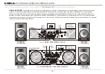
SPADE CONNECTOR: (Figure 11)

When connecting your speakers to the amplifier using spade connector, unscrew the red and black caps on 
the binding post, be sure not to completely remove or unscrew the red and black caps. Insert the spade 
connector into the binding post and tighten the caps down on the spade connector. To reduce the risk of 
shock or damage to your amplifier, be sure that the wire connected to one binding post does not come in 
contact with that of another. 

MONO BRIDGE CONNECTIONS:

Mono bridge operation connections will follow the above descriptions, however, when operating in mono 
bridge operation the speaker connections will run between the two positive (red) leads. Use channel two 
positive output terminal for the speaker’s negative connection and the channel one positive output terminal 
for the speaker’s positive connection.

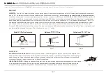
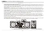
Typical speaker output using bare wire. 
Insert bare wire into the binding post and tighten. 

Typical speaker output using  spade connectors. 
Insert bare wire into the binding post and tighten.  

Figure

 11

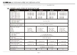
STEREO CONNECTIONS USING THE NEUTRIK SPEAKON OUTPUT CONNECTORS:

Recent regulatory requirements in Europe have outlawed the use of the dual banana plug and force amplifier users to terminate their speaker cables with spade lugs 
or bare wire ends. This is not advantageous to most users that want to reconfigure their systems or quickly change out an amplifier. The Neutrik Speakon connector 
provides the most convenient solution to this problem, eliminating the need for spade lugs or bare wire end cables. Major speaker manufacturers have been using 
Speakon connectors on their products for years, so chances you are ready to use the Speakon connection. With Speakon connectors, you can connect straight from 
the amplifier to the speaker. The Speakon connector used on this amplifier meets all known safety regulations. Once wired correctly, the connector cannot be plugged 
in backwards, causing the type of inverted polarity situations that have become common with banana hookups. This connection will provide a safe, secure and 
reliable method of connecting your speakers to your new amplifier. You can purchase the Speakon NL4FC connectors from your local audio dealer.

page 7

1/5"
13mm

Figure

 10

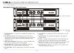
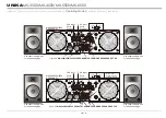
Introduction      Front Panel      Rear Panel      

      Speakon Assembly      Operating Modes      Protection      Features      Specifications

Set Up

UNiKA

 MX-3500/MX-4500/MX-5500/MX-6500

Summary of Contents for MX Series

Page 1: ...er and safe operation of your new amplifier MX Series MX 3500 MX 4500 MX 5500 MX 6500 Made in Taiwan Professional Power Amplifiers Index 02 Introduction 03 Front Panel 04 Rear Panel 6 Set Up 0 08 Spea...

Page 2: ...ez les avertissements suppl mentaries situ s dans le guide Ce symbole est utilis pour indiquer l utilisateur qu il trouvera d importantes instructions importantes sur l utilisation et l entretien de l...

Page 3: ...maged B Objects have fallen or liquid has been spilled into the unit C The appliance has been exposed to rain or water D The fixture does not appear to operate normally or exhibits a marked change in...

Page 4: ...d LED indicates Parallel Mode Green LED indicates Stereo Mode Yellow LED indicates Bridge Mode 5 AC Power Switch MX Series amplifiers have a front panel AC mains power switch 6 Limiter Switch You can...

Page 5: ...ifier for Stereo Parallel or Bridged Mode operation Amplifiers are factory configured for Stereo Mode See section on Mode Selection for more information 16 Channel 1 Balanced 1 4 TRS XLR Input Connect...

Page 6: ...may reduce the buzz that is caused from an electrical 50Hz 60Hz cycle 21 AC POWER Cord Plug this cable into a standard 110V wall outlet Be sure that the supplied voltage in your area matches the ampli...

Page 7: ...vice For example Connect a XLR cable to the input of channel one You may now connect a XLR cable from the channel one Input Thru jack to the input jack of another amplifier s channel one input This wi...

Page 8: ...un between the two positive red leads Use channel two positive output terminal for the speaker s negative connection and the channel one positive output terminal for the speaker s positive connection...

Page 9: ...match the positive and negative leads of each wire Figure 16 5 Slide the connector insert B into the connector housing A making sure that the large notch on the outer edge of the insert lines up with...

Page 10: ...plifier Be sure that your front gain controls are turned down to their lowest level fully counter clockwise Turn your amplifier on Turn your input source level up Use your front gain controls to regul...

Page 11: ...idge switch to the Mono Bridge position Connect input signal to channel one Connect your speaker across the red output binding post on the rear of your amplifier Turn your equipment on your amplifier...

Page 12: ...500 REAR PANEL CH 2 Input MX 4500 5500 6500 REAR PANEL PARALLEL MONO Parallel ties the two channel line inputs together so that they will both be driven by the same signal without the need for externa...

Page 13: ...ing never run the amplifier below 2 ohms in this mode Set up this mode as you would a standard Stereo set up Be sure both channels are set to SUBWOOF In this mode you may use the frequency adjustment...

Page 14: ...POS NEG CH 2 PINOUT 2 2 POS NEG CH 2 1 2 POS NEG BRIDGE 1 1 POS NEG CH 1 CH 1 CH 2 CH 1 CH 2 GAIN 0 775V 1 44V 1V page 13 Use either the bare wire or the banana plugs Use either the bare wire or the b...

Page 15: ...er channel Clipping should be kept to a reasonable minimum An amplifier s peak current draw at full output power into 2 ohms is several times what the normal draw is but its various protection circuit...

Page 16: ...D LIFT SWITCH MX 3500 Only Applying or lifting the ground switch will change level for background noise and hum if the noise level remains the same in either position better to keep the ground lift sw...

Page 17: ...1 KHz 1 THD 8 ohm 1 KHz 1 THD 2400W RMS Stereo 2000W RMS Stereo 1200W RMS Stereo 4800W RMS 4000W RMS 5 25 13 3cm 19 48 3cm 18 3 46 5cm 68 6lbs 31 25kgs 28 23A 230V AC 47 25A 230V AC 1900W RMS Stereo 1...

Page 18: ...Professional Power Amplifiers UNiKA...

Reviews: