background image

page 7

Figure

 10  

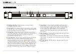
Typical Stereo Output Connections

SPEAKERS

2 OHM MINIMUM

SPEAKERS

2 OHM MINIMUM

OPERATING MODES 

STEREO OPERATION : 

Page 7/Figure 10 details an example of a typical stereo set-up. Connect your inputs into channels one and two of the amplifier. 

Connect your speakers to the outputs on the rear of the amplifier. Be sure that your front gain controls are turned down to their lowest level (fully counter-
clockwise). Turn your amplifier on. Turn your input source level up. Use your front gain controls to regulate the output volume. Be sure not to raise the volume to 
the clip level, however an intermittent clip signal is acceptable.

MONO BRIDGE OPERATION : 

Page 7/Figure 11 details a mono bridge set-up. Be sure your amplifier and all other audio equipment are powered down. 

Press the Stereo/Mono Bridge switch to the Mono Bridge position. Connect an input signal to channel one. Connect your speaker across the red output binding 
post on the rear of your amplifier. Turn your equipment on (your amplifier should always be the last item you turn on). Apply an input source signal to your 
amplifier. Use the channel one gain control to regulate your amplifier output.

Important Precautions     Introduction

Front Panel     Rear Panel     Set Up     

     Protection     Features     Specifications


Operating Modes

PA-500 
REAR PANEL

SPEAKERS

4 OHM MINIMUM

PA-500 
REAR PANEL

Figure

 11  

Typical Mono Bridge Set-Up

CH-1 Input

CH-2 Input

STEREO

AMP MODE

BRIDGE

CH-1 Input
Only

STEREO

AMP MODE

BRIDGE

UNiKA

 PA-500

PUSH

PUSH

4 Ohms/Ch

Minimum

Stereo Mode

8 Ohms

Minimum

Bridge Mode

100VAC

50-60Hz

875VA

FUSE

T250V

7A  L

CAUTION: REPLACE WITH SAME TYPE FUSE AND RATING

ATTENTION: RISQUE DE CHOC ELECTRIQUE - NE PAS OUVRIR

Balanced

Balanced

STEREO

AMP MODE

BRIDGE

CH 1  INPUT

CH 2  INPUT

CAUTION

RISK OF ELECTRIC SHOCK

DO NOT OPEN

Designed and developed in USA  Manufactured in Taiwan

CH 2

BRIDGE

CH 1

_

_

_

+

+
+

WARNING: TO REDUCE THE RISK OF FIRE OR ELECTRIC SHOCK DO NOT EXPOSE TO RAIN OR MOISTURE

!

PUSH

PUSH

4 Ohms/Ch

Minimum

Stereo Mode

8 Ohms

Minimum

Bridge Mode

100VAC

50-60Hz

875VA

FUSE

T250V

7A  L

CAUTION: REPLACE WITH SAME TYPE FUSE AND RATING

ATTENTION: RISQUE DE CHOC ELECTRIQUE - NE PAS OUVRIR

Balanced

Balanced

STEREO

AMP MODE

BRIDGE

CH 1  INPUT

CH 2  INPUT

CAUTION

RISK OF ELECTRIC SHOCK

DO NOT OPEN

Designed and developed in USA  Manufactured in Taiwan

CH 2

BRIDGE

CH 1

_

_

_

+

+
+

WARNING: TO REDUCE THE RISK OF FIRE OR ELECTRIC SHOCK DO NOT EXPOSE TO RAIN OR MOISTURE

!
Summary of Contents for PA Series

Page 1: ...ur new amplifier PA Series PA 500 Made in Taiwan Professional Power Amplifiers Index 02 Important Precautions Introduction 02 03 Front Panel 04 Rear Panel 05 Set Up 07 Operating Modes 08 Protection 08...

Page 2: ...pl mentaries situ s dans le guide Ce symbole est utilis pour indiquer l utilisateur qu il trouvera d importantes instructions importantes sur l utilisation et l entretien de l appareil dans la litt ra...

Page 3: ...ower supply cord or the plug has been damaged B Objects have fallen or liquid has been spilled into the unit C The appliance has been exposed to rain or water D The fixture does not appear to operate...

Page 4: ...t in red when the protection circuit detects output short circuit or DC leakage If it turns on red and does not change to blue please contact the service center 5 Clip Indicator The red clip LED will...

Page 5: ...o by an authorized audio service technician 13 AC Power Input IEC AC power inlet connector plug this cable in to a standard 110V or 220V wall outlet Be sure that supplied voltage matches that of the r...

Page 6: ...s on the rear of the amplifier The speaker wire may be connected by bare wire directly connected usually for permanent connections banana plug or spade connector Connections are made to channel one an...

Page 7: ...When connecting your speakers to the amplifier using spade connector unscrew the red and black caps on the binding post be sure not to completely remove or unscrew the red and black caps Insert the s...

Page 8: ...nel one gain control to regulate your amplifier output Important Precautions Introduction Front Panel Rear Panel Set Up Protection Features Specifications Operating Modes PA 500 REAR PANEL SPEAKERS 4...

Page 9: ...t circuit protection the ACTIVE LED will light indicating amplifier fault Channel output during the Short Circuit Protection will be interrupted i e no sound output Short Circuit Protection can usuall...

Page 10: ...quency Response 20Hz 20KHz Total Harmonic Distortion Crosstalk 1KHz Damping Factor Output Circuitry Input Impedance Power Supply Dimensions H W D Weight Rack Space Power Consumption Maximum Output Pow...

Page 11: ...page 10 Important Precautions Introduction Front Panel Rear Panel Set Up Operating Modes Protection Features Specifications UNiKA PA 500...

Page 12: ...Professional Power Amplifiers UNiKA...

Reviews: