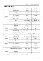
Unilumin UpadIV2, Product Manual
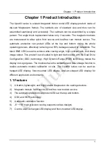
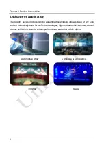
The Unilumin Upad IV2 is a cutting-edge LED display perfect for various events and installations. Easily set up and operate with the Product Manual available for free download on our website. Get your hands on this manual to unlock the full potential of your Upad IV2 at 88.208.23.73:8080.
Share
Download


Reviews:
No comments
Related manuals for UpadIV2

300 Series
Brand: LaCie Pages: 15

S243HL - Bmii Widescreen Slim WLED Display
Brand: Acer Pages: 2

B247Y
Brand: Acer Pages: 2

B243H
Brand: Acer Pages: 2

B248Y
Brand: Acer Pages: 2

CB271H
Brand: Acer Pages: 2

CB272U
Brand: Acer Pages: 3

CB242Y
Brand: Acer Pages: 15

BE270U
Brand: Acer Pages: 4

B247Y
Brand: Acer Pages: 28

EI242QR
Brand: Acer Pages: 16

Computer monitor
Brand: Acer Pages: 20

B248Y
Brand: Acer Pages: 29

B277
Brand: Acer Pages: 18

CB242Y
Brand: Acer Pages: 28

B227Q
Brand: Acer Pages: 35

DV650C
Brand: Acer Pages: 50

A181HL
Brand: Acer Pages: 2


