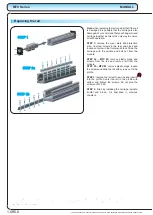
Replacing the floating bearing
STEP 1:
remove the cover plate and shaft key if
necessary.
STEP 2:
remove four screws attaching the frontal
end block to the profile and the set screw securing
the bearing.
Remove frontal end block.
STEP 3:
remove the circlip and bearing from the
shaft. Do not pull the bearing by outer ring!
STEP 4:
put new bearing on the spindle and secure
it with circlip. Do not push the bearing by the outer
ring.
STEP 5:
slide the frontal end block back in the
place and secure it with screws. Secure the bearing
with the set screw. Have the carriage as close as
possible to the frontal end block during this step.
STEP 6:
attach the protection strip and cover plate
to the module as it is described in previous
chapters.
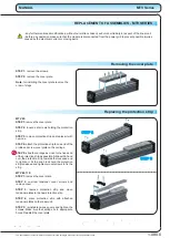
Removing the spindle and spindle nut
STEP 1:
remove the frontal end block and the
floating bearing as described in the previous
chapters.
STEP 2:
move the carriage as close to the end of
the spindle as possible. Remove key holding screw
and nut key. Remove the carriage nut and the ball
nut.
STEP 2 MTV80:
remove the screws in the rear end
block and slide the carriage to that end to unscrew
the cariage nut.
STEP 3:
loosen the locking set screw on the side of
the rear end block and remove the bearing cover.
STEP 3 MTV80:
remove the spindle, ball nut and
the rear end block. Loosen locking set screw in the
side of the rear end block. Remove the ball nut from
the spindle.
STEP 4:
slide the spindle with fixed bearing out of
the rear end block.
Note:
when removing the ball nut put it on the tube
that has outer diameter the same as is inner
diameter of the spindle so that the balls will not fall
out.
1.085.0
MTV Series
MANUAL
Note:
all the screws (except set screws) must be glued (Loctite 243) and screwed
with the torque specified in the table on page 1.005.0 unless written otherwise at
the individual steps.
STEP 2
STEP 3
STEP 2
STEP 3
STEP 4
The specifications in order to improve the products in this catalogue are subject to change without notice.


