background image


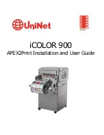
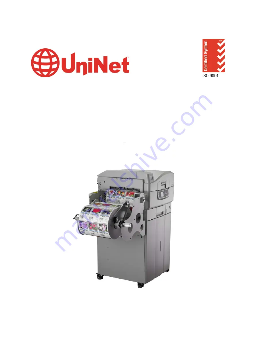
iCOLOR 900 

APEX2Print Installation and User Guide 

Summary of Contents for iCOLOR 900

Page 1: ...iCOLOR 900 APEX2Print Installation and User Guide ...

Page 2: ...he following There are no applications installed or currently running There are no antivirus programs installed No software programs are blocking the Port 80 such as GoToMeeting WebEx TeamViewer etc The computer you re planning to install the software on has the printer and feeder on the same network You will need 2 static IP addresses and 3 network cables Ensure your user account has Administrato...

Page 3: ...ace 29 8 First Time Setup 30 a Setting up the IP Addresses 30 b Input IP addresses into APEX2Print 32 c Selecting a Media ID 32 d Setting up the Cost Calculator 34 e Changing Units of Measurement 35 f Changing the Color Registration 36 g How to View Cost Report 39 h Saving and Loading Page Information 41 9 Before Printing 42 a Measuring your Media 42 b Selecting Media 43 c Sensor Calibration 44 10...

Page 4: ...reating New Media 64 b Editing a newly created Media ID 67 Replacement of Consumables and Maintenance 70 a Replacing the Fuser 70 b Replacing the Transfer Belt 70 c Replacing the Waste Toner Bottle 72 d Cleaning the LED Heads 73 Printing Options 74 a Nesting 74 b Rip Rotate Options 83 c Rip Scaling Options 86 Paper Sensor Error Codes 88 i Help Button 88 ii Feeder Error Messages 88 iii Feeder Panel...

Page 5: ...ng Glue Residue from the Feeder Unit 99 Adjusting Guide Width 101 Manually Adjusting the Guide Width 109 Uninstalling APEX2Print 110 Troubleshooting 112 a How to Change the Settings User 112 b How to Change the Settings Administrator 113 c Exit Speed Adjustment 114 5 ...

Page 6: ...nd unknown that may exist in connection with the provisions of the goods and services provided hereunder by Uninet and that such voluntary risk allocation represents a fundamental part of the agreement reached between Uninet with the purchaser Uninet shall not be liable for any special direct or indirect incidental consequential exemplary punitive or any similar or other damages of any nature suff...

Page 7: ...ed media papers films toners inks fusers or belts inadequate preventative maintenance unauthorized modifications or unauthorized maintenance Such conditions shall render this warranty void and otherwise release Uninet from its liability under this Product warranty Consumables are non warranty items All product returned to factory must be accompanied by an RMA number obtained by calling the Uninet ...

Page 8: ...nded outlet If the plug does not fit the outlet may be an older non grounded type Contact an electrician to have the outlet replaced Do not use an adapter to defeat the grounding Install the product near an easily accessible power outlet Avoid damaging the power cord Do not put anything on it or place it where it will be walked on If the cord becomes damaged or frayed replace it immediately If you...

Page 9: ... total current rating amperes of all connected equipment is less than the maximum rating of the extension cable power strip or wall outlet If the product is already supplied with a fitted power strip then no additional power strip or extension cable should be used to connect to the mains wall outlet Otherwise fire or shock may occur Ensure the power cable is routed so as not to be damaged or cause...

Page 10: ...f the battery is replaced by an incorrect type The product battery should not require replacement during the life of the product Do not throw toner cartridges or image drum cartridges into a fire as you may receive burns from a dust explosion After installing additional memory hard disk drive or any other internally fitted option any covers removed or doors opened must be closed or replaced and se...

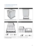
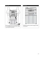
Page 11: ...TEP 1 of 4 STEP 2 of 4 Cut the ties and remove the tape from the box Lift the top sleeve upwards exposing the feeder STEP 3 of 4 STEP 4 of 4 Using two or three people lift the feeder out of the bottom foam packaging Place the feeder on a flat level surface 11 ...

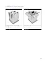
Page 12: ...b Unpacking and Setting Up the Printer STEP 1 of 23 STEP 2 of 23 Cut the ties and remove the tape from the printer box Remove the top sleeve STEP 3 of 23 STEP 4 of 23 12 ...

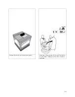
Page 13: ...Remove the accessory box and corner pieces Using two or three people lift the printer and place it on the feeder making sure the printer is level on the feeder 13 ...

Page 14: ... 16 STEP 6 of 16 When placing the printer on the feeder ensure you are aligning the printer with the pins located on the top back of the feeder ICOLOR 900 should be similar to this diagram when full assembled 14 ...

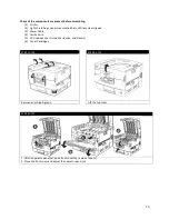
Page 15: ...ens cleaning pad 3 Power Cable 4 Ferrite Core 5 CD includes User Guide Warranties and Drivers 6 Toner Cartridges STEP 7 of 23 STEP 8 of 23 Remove any shipping tape Lift the top cover STEP 9 of 23 1 Lift the operator panel a open front cover b remove tape c 2 Close the front cover and adjust the operator panel d 15 ...

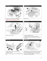
Page 16: ... remove colored seals a NOTE Be sure all tape is removed from image drum cartridges STEP 14 of 23 STEP 15 of 23 1 Shake toner cartridge from side to side to distribute toner a 2 Remove sealing tape from toner cartridge bottom b Align the notch on the end of the toner cartridge with the tab a in the image drum and then lower the toner cartridge into the image drum Press down to make sure it is seat...

Page 17: ...idge with blue lever 2 Repeat these steps for remaining toner cartridges Close the top cover STEP 18 of 23 STEP 19 of 23 1 Pull out the paper tray a 2 Remove the colored shipping retainer b 3 Insert the appropriate media size label c Load paper 17 ...

Page 18: ...eeder 2 Insert the power cable into the printer 3 Turn the printer on B power switch In order to reduce electromagnetic interference noise that interferes with TVs or other appliances you must place the included ferrite core on the network cable 1 Loop the cable as shown placing the core about 1 inch from the connector on the printer end Note The network cable is not provided 2 Connect the network...

Page 19: ...IMPORTANT Use with Media with a maximum width of 12 9 Maximum Print width 12 6 Identify the three doors and cover for the feeder Guide Door Media Door Cutter Cover Extension Arm Load Door Spindle Pin Guide Channels 19 ...

Page 20: ...der against the back red Extension Arm Lift the Extension Arm back up into position making sure both the Plunger and Extension Arm lock The Extension Arm should be rubbing on the roll slightly to provide some back tension drag This also ensures the Guide Channels will be tight to the media STEP 3 of 7 STEP 4 of 7 Open the Load Door at the bottom front of the feeder by releasing the two yellow latc...

Page 21: ...not fit between the Guide Channels The paper should lay flat against the back of the feeder If the media does not fit re measure the width of the roll and use the software to send the width to the printer Close the Guide Channels and Load Door Press the Load button to load the media The roll will begin to load and cut off a section for proper alignment Using caution open the cutter door and carefu...

Page 22: ...uter with an Administrator account Navigate to the installation folder provided by your vendor DO NOT insert the dongles at this point STEP 2 of 8 The control panel screen should look like this after a few moments Press the Done button The media will then load and the feeder will return to Idle status 22 ...

Page 23: ...Navigate to the 2 Install RIP vR2 Folder Run the Prepare_Uninet_RIP_v2 1 exe file 23 ...

Page 24: ...STEP 3 of 8 The KEYLOK and Sentinel Drivers will install 24 ...

Page 25: ...STEP 4 of 8 The Dongles should be inserted at this stage Click the Install Dongles then Click to Continue button 25 ...

Page 26: ...STEP 5 of 8 Click Done STEP 6 of 8 26 ...

Page 27: ...Navigate to the 3 Install APEX2Print folder Run the APEX2Print_Install msi file Click Next 27 ...

Page 28: ...STEP 7 of 8 Click Next on the Select Installation Folder Window Click Next on the Confirm Installation Window STEP 8 of 8 The Installation will proceed Click Close on the Installation Complete Window 28 ...

Page 29: ...7 APEX2Print Interface 1 Toolbar 2 Preview Screen 3 Print Settings 4 Image List 5 Rip Options Note Before launching APEX2Print make sure the two dongles are inserted 29 ...

Page 30: ...r the printer and feeder Setting the IP address on the ICOLOR 900 STEP 2 STEP 2 Press Menu on the printer display panel to enter the printer menu Scroll down and select Admin Setup to enter Using the up arrow keys enter the password aaaaaa six lower case a s Select Enter STEP 3 STEP 4 Select the Network Setup menu Scroll down to the IP Address and select Enter 30 ...

Page 31: ...n arrow key and select it 3 Press the down arrow key to IP Address 4 Hold down the Select key until an arrow flashes beside the IP address Set each part of the IP address as required using the UP and DOWN arrows Press save after each entry and then select to move to the next set of numbers 5 When the address is set hit save 6 Hit the down arrow key and select exit 6 Press the down arrow key again ...

Page 32: ...addresses into APEX2Print c Selecting a Media ID STEP 1 From the APEX2Print toolbar click on Setup Options IP Addresses Step 2 Input the IP Addresses that were setup for the Printer and Feeder Click Save STEP 1 32 ...

Page 33: ...er to the appendix To select the media of choice click Media tab on the APEX2Print toolbar Select the correct Media ID you are using and double click on that Media ID to use the predefined settings required for using that specific media type 33 ...

Page 34: ...ost Calculator STEP 1 From the APEX2Print toolbar click on Setup Options Cost Calculator Step 2 Input the price paid for each consumable This will calculate the cost per label This value will appear in the Image List 34 ...

Page 35: ... Changing Units of Measurement STEP 1 From the APEX2Print toolbar click on Setup Options Display Options Step 2 Choose Measurement Units in either Imperial in or Metric mm To apply settings click Save 35 ...

Page 36: ...f Changing the Color Registration STEP 1 From the APEX2Print toolbar click on Setup Options Color Registration STEP 2 Click Print Registration Plot 36 ...

Page 37: ...in determining the proper registration values across CMY Using a printer s loupe or best judgment the correct values can be determined In this case the correct values are as follows C 6 M 4 Y 0 this is because the pixels are perfectly filled within the boxes 37 ...

Page 38: ...STEP 4 With the values determined C 6 M 4 Y 0 The following adjustments can be made to the Color Registration Form Click Apply to set 38 ...

Page 39: ...he TOTAL LENGTH STEP 1 Cost Calculation Report General Information Media Name 11001 Media Width 12 9 in Gutter 0 125 in Alley 0 125 in Job Set 1 Column 1 of 3 PDF Name 2x2 pdf Label Size 2 x 2 in K Percentage 2 2 C Percentage 37 0 M Percentage 13 1 Y Percentage 5 9 Toner Cost per Label CMYK 0 0075 Total Length Column 1 1 77 feet Total Labels To Print 10 Total Toner Cost CMYK 0 0752 Total Cost per ...

Page 40: ...0 1479 Total Cost per Label 0 0158 Total Cost per Job 0 16 Job 2 Total Cost 0 16 Job Set 1 Column 3 of 3 PDF Name 2x2_pink pdf Label Size 2 x 2 in K Percentage 2 3 C Percentage 13 2 M Percentage 48 5 Y Percentage 6 0 Toner Cost per Label CMYK 0 0091 Total Length Column 3 1 77 feet Total Labels To Print 10 Total Toner Cost CMYK 0 0905 Total Cost per Label 0 0101 Total Cost per Job 0 10 Job 3 Total ...

Page 41: ...s can be saved and loaded for later use Click File Save Page Information Select a location Type a file name Click Save To Load a Page Information file click File Load Page Information Select the Page Information file s location Select the Page Information file Click Open 41 ...

Page 42: ... alignment Measure this distance and Measure this distance and input into Gutter input into Alley Option 2 For Die Cut labels without gaps Uses black line for sensor alignment Measure the thickness of the black line Input this value into Gutter If the Label has more than one column of labels measure distance between labels horizontal and input value into Alley Gutter Measures the distance between ...

Page 43: ... toolbar click Media The following media list will open This media list holds Medias that have been certified by Uninet After selecting the type of material and the texture of your media roll click on the type of media that will be used or match it to the Media ID To create or edit custom media please refer to the appendix 43 ...

Page 44: ...ll use the Gap Sensor see Step 2 of 6 Die cut with black lines on the back will use the Back Sensor Die cut with black lines on the top will use the Top Sensor see Step 2 of 6 STEP 1 In APEX2Print select Die Cut Mode If printing on regular media Die Cut mode does not need to be selected 44 ...

Page 45: ...STEP 2 Select correct sensor according to the type of media being used If the calibration sensor is red you must calibrate the media 45 ...

Page 46: ... the paper shown in the photo as the blue arrow about one inch below the sensor Red arrow For Gap Sensor Line up the gap Blue arrow of the labels about one inch from the sensor Red arrow Give some slack to the roll of paper directly underneath the sensor before calibrating This ensures the rollers are not pulling the weight of the roll while calibrating STEP 4 When the media is properly loaded and...

Page 47: ... previously stored in the feeder from the last use press Copy Feeder Settings To Media Library You can also manually input the values for Sensor Window and gain under the Media Library Settings Then select Copy Media Library Settings to Media Library to update the values to the feeder Note that only the right side Media Library Settings can be modified 47 ...

Page 48: ...STEP 6 After calibration manually rewind the roll until the paper is inside the red arms The feeder will read Require Load Press the Load button 48 ...

Page 49: ...ically where the printer starts printing the labels 1 Print more than 20 50 8cm of labels for the first print Make sure the proper values for paper width gutter and alley measurements are inserted into APEX2Print 2 Check the start position 20 50 8cm The 20 of header color patterns for calibration The gap in between labels should be in line with the gap on the label or back sensor line If the label...

Page 50: ... multiple PDF files all of the same dimensions the selected files will be displayed in the Preview Screen Notice that multiple files are aligned in columns Once all PDF files have been added and the entire page Information adjustments have been made click Print 50 ...

Page 51: ...th If the new media width is not the same size then the Feeder Media Size Mismatch window will display Select OK to Unload Media If there is no media loaded this action still needs to be completed STEP 3 of 4 After the media unload action has completed press Done on the feeder unit Click OK to print 51 ...

Page 52: ...STEP 4 of 4 If Done is not selected on the feeder unit the printer will remain in a busy state and display a Feeder Not Ready window Press Done on the feeder unit Click OK 52 ...

Page 53: ...Appendix 53 ...

Page 54: ...registration Front Panel LCD interface Web management system torque Auto adjusting form synchronization Rewinder System Output roll maximum diameter 12 inches 305 mm Core inside diameter 3 inches 76 2 mm Maximum output roll weight 60 lbs 27 2 kg Dimensions H X W X D Printer Feeder 46 3 x 25 7 x24 9 1177 mm x 654 mm x 633 mm Rewinder 16 4 x 19 7 x 21 415 mm x 500 mm x 533 mm Weight Printer Feeder 3...

Page 55: ...h over print or printing into the gap and alley we actually cut the label first and print over top the substrate Here is how you do such a procedure The Trim Box is the size of the die cut label The die cut dimensions are of course the choice of the printer and can be ordered from any converter 4 Letter size sheets at 5 coverage Printer ships with a 7 500 page set of starter toners 5 Based on 500 ...

Page 56: ... New Alley 101 9 3 175 103 9 1 175 101 6 3 175 103 9 0 875 Add these figures into APEX2Print with the gap sensor on and mm selected Make sure you have a good delta reading from your sensor calibration routine Once you have done the calibration you do not need to run it again Start position and left right will be a separate adjustment Run a test Job On the third page observe the start position and ...

Page 57: ...57 ...

Page 58: ...eft margin that will blink Press up or down arrow to change options Press Deselect to save changes blinking will stop 4 To Exit scroll down to exit then select If at any time you need to re boot the printer without turning the unit on and off by the rear power switch press and hold the middle button for 2 seconds Printer will go into soft power off mode Press middle button again holding for 2 seco...

Page 59: ...PAGE 3 59 ...

Page 60: ...e media path and ensure that the media is loaded into the printer correctly also ensure that the media is located under the media sensors If the cart menu continues to display this error remove all media and reboot the printer Errors 20 to 29 Swing Errors If the feeder menu displays errors 20 to 29 check the media path and ensure that the media is loaded into the printer correctly and the media is...

Page 61: ...for a soft shutdown You can then press this button again for a restart or use the Power switch to turn off the printer completely Ready light On indicates ready to print Flashing indicates processing print data Off indicates unable to receive data offline Attention light Off indicates normal operation Flashing indicates error s present but printing can continue On indicates error s present and pri...

Page 62: ... HELP button Install Tray The printer has tried to take paper from a tray that has been removed Ensure that tray is correctly located or put tray loaded with paper back into the printer Open Cover Paper Remains Please see HELP for details Additional paper has been detected after a paper jam has been cleared Open side cover to check for additional paper You can access help details by pressing the H...

Page 63: ...ns at each level can be scrolled through by moving the highlight with the Up arrow Down arrow buttons and a highlighted option at that level can be selected by pressing the Enter button When the lowest level menu has been selected you can change the setting for that menu by selecting the required highlighted value from a list or by entering a numeric value In other cases you can display or print c...

Page 64: ...o create and edit new Media ID Custom Media ID a Creating New Media STEP 1 of 5 To create a new media click Media Tab on the APEX2Print toolbar Select the correct media ID and right click on any Media ID 64 ...

Page 65: ...STEP 2 of 5 The Creating a New User Media Entry window will open Note All 3 User Media fields must be filled before a new media entry can be updated into the media list STEP 3of 5 65 ...

Page 66: ...on is now available Make the necessary adjustments to the Media Type field and the Media Weight Please check the Appendix for a media guide description When the necessary changes have been made click Update Create This Media STEP 4 of 5 The new media will be displayed in the Media List 66 ...

Page 67: ...TEP 5 of 5 There is an option that allows for only the new media to be displayed Check the Show Only User Media box to view only new custom media IDs STEP 1 of 4 If the new media entry needs to be edited right click on the new Media ID 67 ...

Page 68: ...STEP 2 of 4 The Creating a New User Media Entry window will display Click Edit STEP 3 of 4 68 ...

Page 69: ...ia button STEP 4 of 4 To delete a new Media ID ensure that the media for deletion is not loaded An Error Deleting Active Media window will display the warning displayed above Click OK Click Media Select another Media ID to load Click Media Right click on the new Media ID for deletion Click Delete This Media 69 ...

Page 70: ...user may be hot Lift the Blue tab up to unlock the fuser Using the handle gently Lift the fuser out of the printer b Replacing the Transfer Belt STEP 1 STEP 2 Turn off the printer Open the top cover CAUTION The fuser is very HOT after the printer has been printing Be careful not to touch it 70 ...

Page 71: ...belt latches to release them Grasp the blue handles and lift the transfer belt out Dispose of it in accordance with local regulations STEP 7 STEP 8 Unpack the new transfer belt grasp the blue handles and lower the left side of the belt into the printer fitting the pins into the guides at the front and back then lower the right side Push down on the belt latches to lock the new belt in place 71 ...

Page 72: ...artridge units back into the printer 1 Close the top cover 2 Turn the Printer on c Replacing the Waste Toner Bottle STEP 1 STEP 2 Open the door and remove the waste toner bottle Follow the instructions on the label to ensure proper disposal 72 ...

Page 73: ...mages white stripes or blurred letters STEP 1 STEP 2 Open the top cover Use the LED cleaner provided with the toner cartridges or a soft lint free cloth to gently wipe each of the four heads 1 Move the cleaner as shown using a fresh section for each pass Be careful not to damage the guards 2 When finished close the top cover 73 ...

Page 74: ...ing Being able to print multiple images on your current media at the same time STEP 1 of 10 Click the Nesting Tab Notice that the Add and Edit buttons have become available and the Print button is now labeled Print Nesting 74 ...

Page 75: ...file or multiple PDF files of the same dimensions size the selected files for nesting will be displayed in the Preview Screen Click Add and the PDF PDFs will be removed from the Preview Screen The job will be stored for printing The Print Nesting button will now display Print Nesting 1 75 ...

Page 76: ...file or multiple PDF files of the same dimensions size the selected files for nesting will be displayed in the Preview Screen Click Add and the PDF PDFs will be removed from the Preview Screen The job will be stored for printing The Print Nesting button will now display Print Nesting 2 76 ...

Page 77: ...en File and select a PDF file or multiple PDF files of the same dimensions size the selected files for nesting will be displayed in the Preview Screen Click Add and the PDF PDFs will be removed from the Preview Screen The job will be stored for printing The Print Nesting button will now display Print Nesting 3 77 ...

Page 78: ...STEP 5 of 10 Notice that 3 jobs have been nested with the Print Nesting 3 button indicator If needed click on Edit to make additional changes to the nested jobs 78 ...

Page 79: ...ishing printers media must pass a certain distance through the printer before printing can occur Between Nested Jobs When printing nested jobs it can be very difficult to differentiate between similar images such as barcodes Adjustments can be made to allow a space of one label between nested jobs End of the Plot This value will remain as the same value from the Beginning of the Plot this will all...

Page 80: ...STEP 7 of 10 The job is ready for printing Click Print Nesting 80 ...

Page 81: ...th If the new media width is not the same size then the Feeder Media Size Mismatch window will display Select OK to Unload Media If there is no media loaded this action still needs to be completed STEP 9 of 10 After the media unload action has completed press Done on the feeder unit Click OK to print 81 ...

Page 82: ...STEP 10 of 10 If Done is not selected on the feeder unit the printer will remain in a busy state and display a Feeder Not Ready window Press Done on the feeder unit Click OK 82 ...

Page 83: ...b Rip Rotate Options STEP 1 When the Rip Rotate Option is set to 0 all PDF files will preview in their original orientation The Rip Rotate Options will allow for the desired orientation 83 ...

Page 84: ...STEP 2 Select the desired rotation value Click Clear in the Image List section STEP 3 Click Open File Select the PDF for rotation 84 ...

Page 85: ...STEP 4 The rotation has been applied to the PDF Adjustments can now be made in the page Information section for correct placement on the Selected Media 85 ...

Page 86: ...c Rip Scaling Options STEP 1 Select the desired scaling values Click Clear in the Image List section STEP 2 Click Open File Select the PDF for scaling 86 ...

Page 87: ...STEP 3 The Preview Screen will display the scaled object 87 ...

Page 88: ...the printer Errors 20 to 29 Swing Errors If the feeder menu displays errors 20 to 29 check the media path and ensure that the media is loaded into the printer correctly and the media is located under the media sensors If the feeder menu continues to display this error remove all media and reboot the printer Errors 30 to 39 Cutter Errors If the feeder menu displays errors 30 to 39 check the media p...

Page 89: ...1 Media not positioned between load sensors properly after load advance Check that media tension is not too tight Status Error 31 Cutter did not leave home position in required time Check paper jam in cutter Status Error 32 Cutter did not finish cut in required time or can t home it Check paper jam in cutter Clearing Paper Jams If you are experiencing frequent paper jams check the following items ...

Page 90: ... i Tray Side Cover STEP 1 STEP 2 Hold the tab turn the paper guide outward Remove the paper jam STEP 3 Close the paper guide 90 ...

Page 91: ... ii Printer Side Cover STEP 1 STEP 2 Open Side Cover Pull release lever and open side cover STEP 3 STEP 4 Remove the paper jam Close the side cover 91 ...

Page 92: ... raise drum basket WARNING Be careful not to touch the fuser unit which may be hot after printing If the fuser unit is hot wait until it cools before attempting to remove any jammed paper STEP 3 STEP 4 Remove the paper jam Unlock the fuser and remove from the machine by lifting upwards 92 ...

Page 93: ...STEP 5 STEP 6 Pull up jam release levers to release paper Turn the lock lever to lock fuser unit STEP 7 STEP 8 Open the face up stacker Open side cover paper exit Release levers 93 ...

Page 94: ...STEP 9 STEP 10 Close side cover and then face up stacker Close image drum basket STEP 11 Close the top cover 94 ...

Page 95: ...Jams STEP 1 STEP 2 If you have a paper jam press Help to find out the error code Open the Side Cover STEP 3 STEP 4 Locate the paper jam Open the Guide Door and Guide Cover Open the two Guide Channels and Load Door 95 ...

Page 96: ... printer is not level Place the printer on a steady level surface Your print media is too light or too heavy Use appropriate media Your print media is damp or charged with static electricity Use media that has been stored in appropriate temperature and humidity conditions Your print media is creased or curled Use appropriate media Decurled media can be used Your print media sheets are not aligned ...

Page 97: ... Thickness and type of paper are inappropriate Set a proper value for Media Weight and Media Type in the menu setup or set one value thicker for Media Weight Partially faded images White spots and lines appear in solid printing Paper is moist or dry Use paper stored in proper temperature and humidity conditions Vertical lines appear The image drum cartridge is damaged Replace the image drum cartri...

Page 98: ...hickness and type of the paper are incorrectly set Set the correct value of Media Type and Media Weight in the menu setup or set one value thicker for Media Weight Glossiness is not uniform The thickness and type of the paper are incorrectly set Set the correct value of Media Type and Media Weight in the menu setup or set one value thicker for Media Weight 98 ...

Page 99: ...rate c The feeder blade does not have a clean cut To fix the three problems shown below you will need to use 99 isopropyl alcohol and a Kimwipe to gently wipe each of the surfaces until the adhesive and residue are removed For access to the cutter blade you will need to remove the cutter blade cover by unscrewing all five screws Using caution wipe the cutter blade until all residue is removed Retu...

Page 100: ...Example 2 Guide Arms Example 3 Cutter Blade Glue Residue Glue Residue 100 ...

Page 101: ...n which will cause the feeder to unload the media it will do this if there is media loaded or not STEP 3 STEP 4 Once the unload operation is complete the control panel will show this screen Open the Media Door Pull the plunger to release the Extension Arm Drop the Extension Arm down and remove the media roll if one is loaded 101 ...

Page 102: ...l adjustment can be made Wait for the Extension Arm to finish adjusting STEP 7 STEP 8 Press the Online Offline button so the control panel shows this screen PRESS and HOLD the Guide button for approximately 3 seconds The control panel should now look like this Press the Open button 60 times each press opens the Extension Arm an additional 0 25mm The Extension Arm will now be open approximately 12 ...

Page 103: ...oll is pushed all the way into the feeder against the back Extension Arm Lift the Extension Arm back up into position making sure both the Plunger and Extension Arm lock STEP 11 STEP 12 The Extension Arm should be rubbing on the roll slightly to provide some back tension drag If it is not Press the Close button on the control panel a few times until the Guide Arm is rubbing slightly Open the Load ...

Page 104: ...Open the Guide Cover and Guide Channels Feed the paper under the orange Tension Swing as shown 104 ...

Page 105: ...distance between the edge of the paper and the Guide Channel is less than 0 5mm on each side and the paper aligned with the right side Guide Channel Ensure the Channel Gap is not too small so that the paper does not fit between the Guide Channels The paper should lay flat against the back of the feeder Use the Open and Close buttons to make an adjustment if necessary Close the Guide Channels Load ...

Page 106: ... the Load button to load the media The roll will begin to load and cut off a section for proper alignment Open the cutter door and while using caution carefully remove the piece of cut paper Close the cutter door Note Depending on the type of media being used the paper may fall inside the feeder Use caution when retrieving cut media CAUTION Do not place hands inside machine while printing or cutti...

Page 107: ...anel screen should look like this after the load finishes STEP 17 STEP 18 The control panel screen should look like this after a few moments Open the Cutter Door and remove the cut piece of waste paper Close the Cutter Door Remove cut piece of media 107 ...

Page 108: ...STEP 21 Close the Guide Door and the system is ready to print 108 ...

Page 109: ...hould be less than 0 5mm on each side of the media These instructions can be used as a quick fix for gaps that are below 0 25 wide If the gap is larger than that go back to the software to adjust the overall width of the roll STEP 1 This image shows that the guides are too wide for the media We will manually adjust the guides using the panel on the feeder STEP 2 First you must press Online to acce...

Page 110: ...Each time open close is pressed the guides open 0 01 0 254mm Once this is done select Exit Note You may need to open and close the Guide Channels Load Door and Guide Cover to see how tight the media is between the Guide Channels Uninstalling APEX2Print For Software Upgrade Use this uninstall before installing the new upgrade 110 ...

Page 111: ...1 of 4 Start Menu Control Panel STEP 2 of 4 Click on Programs and Features STEP 3 of 4 Select APEX2Print Right Click Select Uninstall STEP 4 of 4 Click Yes on the window prompt APEX2Print will uninstall 111 ...

Page 112: ...ou wish to view is displayed Then proceed as follows 1 Press Enter to enter the menu 2 Use the up and down MENU buttons on the control panel to scroll through the menus When the item you want to change is displayed press Enter to view the sub menus for that item 3 Use the up and down MENU buttons to move up and down through the sub menu items When the item you want to change is displayed press Ent...

Page 113: ...g the up and down MENU buttons scroll to the required letter digit b Press the Enter button to input and move to the next letter digit c Repeat steps a and b until all letters digits are entered 4 Press the Enter button 5 Press the up or down MENU button until the category you want to change is displayed 6 Press the Enter button 7 Press the up or down MENU button until the item you want to change ...

Page 114: ... STEP 1 STEP 2 Select Menu on the printer menu Scroll down the menu and select Calibration STEP 5 Adjust the exit speed by increasing the number in increments of two Select Enter and then Online STEP 3 STEP 4 Scroll down the Calibration menu Select Exit Speed Adjustment 114 ...

Reviews: