


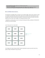


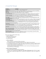


In this example we have a die cut with dimensions of 101.9h x 101.9w that we received from a
converter. The overprint area is 1mm larger than the actual label on all sides, thus adding 2mm total to
the height and 2mm total to the width. This gives us a label image size of 103.9 x 103.9.
The gap and alley are each measured at 3.175.
TBh – Trim Box height TBw – Trim Box width MBh – Media Box height MBw – Media Box width
G – Gap or Gutter A – Alley
Here is how you calculate for the new gap and new alley used for over bleed.
TBh + G – MBh = New Gap and TBw + G – MBw = New Alley
101.9 + 3.175 – 103.9 = 1.175 101.6 + 3.175 – 103.9 = 0.875
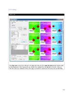
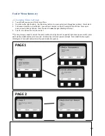
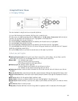
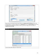
Add these figures into APEX2Print with the gap sensor on and mm selected. Make sure you have a good
delta reading from your sensor calibration routine. Once you have done the calibration you do not need
to run it again.
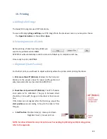
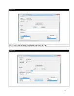
Start position and left/right will be a separate adjustment.
Run a test Job. On the third page observe the start position and adjust it so the image is approximately
1mm above the die cut label. Do the same for the left/right position; make sure that down the left hand
column you see the image outside the die cut label by approximately 1mm.
You should now be running a full bleed label. You will see movement as per spec but every label should
stay within the limits.
56
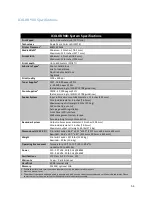
Summary of Contents for iCOLOR 900
Page 1: ...iCOLOR 900 APEX2Print Installation and User Guide ...
Page 23: ...Navigate to the 2 Install RIP vR2 Folder Run the Prepare_Uninet_RIP_v2 1 exe file 23 ...
Page 24: ...STEP 3 of 8 The KEYLOK and Sentinel Drivers will install 24 ...
Page 26: ...STEP 5 of 8 Click Done STEP 6 of 8 26 ...
Page 27: ...Navigate to the 3 Install APEX2Print folder Run the APEX2Print_Install msi file Click Next 27 ...
Page 53: ...Appendix 53 ...
Page 57: ...57 ...
Page 59: ...PAGE 3 59 ...
Page 68: ...STEP 2 of 4 The Creating a New User Media Entry window will display Click Edit STEP 3 of 4 68 ...
Page 80: ...STEP 7 of 10 The job is ready for printing Click Print Nesting 80 ...
Page 87: ...STEP 3 The Preview Screen will display the scaled object 87 ...
Page 100: ...Example 2 Guide Arms Example 3 Cutter Blade Glue Residue Glue Residue 100 ...
Page 108: ...STEP 21 Close the Guide Door and the system is ready to print 108 ...


