background image

Pioneering solutions for 
total power protection

MINI

power

P

LUS

User Manual

Summary of Contents for Minipower Plus Rack

Page 1: ...Pioneering solutions for total power protection MINIpower PLUS User Manual ...

Page 2: ......

Page 3: ...rPLUS User Manual Dated 08 03 12 Document Control ISSUE DATE REVISION SUMMARY Draft A 7 11 11 First draft issued for comments Draft A1 9 2 12 Second draft incorporating rack mounted model Issue 1 0 08 03 12 Initial release ...

Page 4: ...o understand manual and will therefore assume no responsibility nor liability for direct indirect or accidental personal or material damage due to any misinterpretation of or accidental mistakes in this manual 2005 Uninterruptible Power Supplies Ltd This manual may not be copied nor reproduced without written permission of Uninterruptible Power Supplies Ltd ...

Page 5: ... Installation Procedure 5 5 3 3 1 Connect the UPS cabinet to the battery cabinet 5 5 3 3 2 Connecting the UPS communication options 5 7 3 3 3 Connect the UPS input output power cables 5 8 3 3 4 Powering ON the UPS 5 11 4 Operation 4 1 Operating Instructions 6 1 4 1 1 Standard installation without the maintenance bypass option fitted 6 1 4 1 2 Installation with Maintenance Bypass option fitted 6 2 ...

Page 6: ...ng software 9 4 7 2 3 SNMP ADAPTER for network management remote monitoring 9 6 7 3 PowerREPORTER management software 9 7 7 3 1 Relay Interface Board 9 8 8 Specifications 8 1 Construction Features 10 1 8 2 Environmental 10 1 8 3 Electrical Input 10 2 8 4 Output Waveform 10 2 8 5 Output When Running on Mains Power 10 2 8 6 Output When Running on Battery Power 10 3 8 7 Battery Operation MINIpowerPLU...

Page 7: ...urrent Ensure that the UPS has been correctly earthed before you connect the mains power supply WARNING If the UPS is delivered without the batteries already fitted it must not be powered up without having first been commissioned by an engineer authorised by the manufacturer WARNING All servicing must be performed by an authorised engineer or other suitably qualified personnel Do not attempt to se...

Page 8: ...1 Safety 1 2 UPS453 01 00 MINIpowerPLUS User Manual Dated 08 03 12 ...

Page 9: ... 8 of this manual 2 2 MINIpowerPLUS Model Range The MINIpowerPLUS system is available in two model ranges MINIpowerPLUS 5000 The MINIpowerPLUS 5000 is available in both Rack mounted and Tower versions and uses up to four 1250VA power modules to offer a system output rating of 1250VA 2500VA 3750VA or 5000VA Each power module requires three batteries which are housed within the UPS cabinet to provid...

Page 10: ...put voltage fluctuations The rectified output from the power factor correction stage is connected to the inverter where it is converted to a clean sinusoidal output voltage with very low distortion The operation of the power factor correction stage is particularly important when operating with very low loads For example with a nominal load of around 50 it is possible to sustain the inverter operat...

Page 11: ... the control software can be configured so that only an error signal is produced without a switchover to battery operation All the UPS operating functions are supervised in real time by a microprocessor which controls and stores certain operating parameters in addition to managing an RS232 computer interface Battery operation If the mains voltage fails or is subject to excessive sag the voltage bo...

Page 12: ...is provided This warranty will be invalidated if the UPS is put into use without having first been commissioned by a fully trained and authorised engineer unless the UPS is supplied with the batteries already fitted and connected This warranty does not apply to any losses or damages caused by misuse abuse negligence neglect unauthorised repair or modification incorrect installation inappropriate e...

Page 13: ...cluding batteries cover Contact the Service Support Hotline on 0800 731 3269 for further details 2 6 Additional Service Maintenance Support In addition to providing support for the MINIpowerPLUS Uninterruptible Power Supplies Ltd are able to provide maintenance and support on a wide range of different UPS products If you are interested in an extended warranty for your MINIpowerPLUS UPS or any othe...

Page 14: ...pspower co uk www upspower co uk Uninterruptible Power Supplies Ltd Bacchus House Calleva Park Aldermaston Berkshire RG7 8EN Tel 0118 981 5151 Name Job Title Company Address Post Code Tel Fax E mail Please contact me to discuss Extended Warranty options for my MINIpowerPLUS UPS Extended warranty options for my UPS System as below Manufacturer Model Nº Rating kVA Replacement Batteries Other please ...

Page 15: ...ntainer in a polythene sheet Upon delivery you should carefully examine the packing containers for signs of physical damage If there are signs of transportation damage you must inform both the carrier and Uninterruptible Power Supplies Ltd immediately WARNING The electrical installation of this UPS system and its peripheral equipment must be carried out by an authorised electrician or other suitab...

Page 16: ...connected If the batteries are ordered and shipped separately they must be fitted by a manufacturer approved engineer as part of the system commissioning procedure 3 1 5 Storage UPS Cabinet storage If you plan to store the UPS cabinet prior to installation it should be kept in a clean dry environment with an ambient temperature between 5 C to 40 C and relative humidity of less than 90 Ideally the ...

Page 17: ...mended that the cabinets are located so that they can be wheeled forward to provide the necessary side and rear access when required This recommendation must be taken into consideration when cabling the equipment so that a sufficient cable length is provided to allow for the prescribed cabinet movement Figure 3 1 shows a space of 900 mm provided at the front of the cabinets This allows adequate ro...

Page 18: ...ear of the unit to allow for adequate cooling air flow and facilitate cabling As the UPS cabinet is 600mm deep this implies a minimum rack depth of 800mm As mentioned above rear access is required for cabling therefore sufficient room should be provided behind the rack to permit easy passage recommended 900mm A similar space is required at the front of the rack to enable the UPS cabinet to be hand...

Page 19: ...et to the battery cabinet In a MINIpowerPLUS 10000 system the UPS batteries are housed in a separate battery cabinet that is connected to the UPS cabinet by three cables In a MINIpowerPLUS 5000 system a separate battery cabinet is an optional facility that is sometimes added to provide an extended autonomy time over and above that available from the standard internal batteries All interconnecting ...

Page 20: ...0 battery connections 1 On the back of the UPS cabinet loosen the two screws securing the battery connector cover plate Slide the cover plate open to expose the battery connectors then retighten the securing screws to hold the cover plate open 2 Connect the flexible braided earth strap provided between the chassis earth studs on both cabinets the studs are located adjacent to the battery connector...

Page 21: ...n interface with a range of monitoring and control software such as the CS121L Adapter Box for WaveMon or other monitoring software using SNMP and MODBUS The remaining connectors 9 pin male provide logic output signals that can be used to drive remote alarms and indication facilities this is normally carried out via a relay interface board See paragraph 7 3 1 The following output signals are provi...

Page 22: ...er power cable the connector can be rewired as shown below in Figure 3 9 MINIpowerPLUS 10000 power cables A ready made cable of approximately 600mm in length fitted with standard IEC connectors is supplied with the UPS If it is necessary to rewire the connector the cable must be a minimum of 4mm and have insulated wires see Figure 3 10 Figure 3 8 UPS input output power receptacles Connecting the U...

Page 23: ...ower connector wiring Figure 3 9 Input Output power connector wiring CAUTION Ensure the UPS input mains supply is isolated before proceeding Never remove the 230 V power plug whilst the UPS is in operation as this would disconnect the earth protection of both the UPS and of the connected loads ...

Page 24: ...is isolated before proceeding Never remove the 230 V power plug whilst the UPS is in operation as this would disconnect the earth protection of both the UPS and of the connected loads Input Cable from mains Output Cable to load Yellow Green Earth 1 Blue N 2 Brown L 3 Brown L 4 Blue N Earth Connection Yellow Green Earth I1 I2 Link Input Output Power Connector Cable Glands Plastic Housing 4x Securin...

Page 25: ...mmediately turn off the input mains power supply disconnect the UPS power connector and seek the manufacturer s advice 4 If the initial power on indications above do not indicate a fault you can connect the load equipment to the UPS output and switch ON the UPS following the Operating Instructions contained in Chapter 4 of this manual Important final checks As current dispersion towards earth of a...

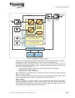
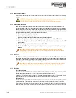
Page 26: ...3 Installation 3 12 UPS453 01 00 MINIpowerPLUS User Manual Dated 08 03 12 ...

Page 27: ...ontrol Panel status indicator will change from red to yellow and then finally remain green c The UPS Control Panel LCD display will show the UPS input and output parameters and appear similar to the example shown in Figure 4 2 4 The UPS is now fully operational and providing your load equipment with a protected backed up supply 5 You can now further monitor the UPS operating parameters using the S...

Page 28: ...UP BYPASS menu as shown on page 4 8 b From the BYPASS menu select and disable Forced Mode 5 The UPS is now fully operational and providing your load equipment with a protected backed up supply 6 You can now further monitor the UPS operating parameters using the STATUS Menu as described in paragraph 4 4 2 To transfer the load from the UPS to the maintenance bypass line 1 Transfer the UPS output to ...

Page 29: ...with an ON OFF button Operating status indicator The area behind the mimic diagram is illuminated by a multi coloured led to indicate the UPS operating status UPS On Mains Normal operating status when the input mains voltage is present On Battery There is no mains power and the UPS is running on its batteries On By pass The UPS internal bypass circuit has been turned on and the UPS output is conne...

Page 30: ...e UPS and contact your service centre Overload Reduce the load until it is within the UPS capacity Solid Red Continuous UPS error or failure ATTENTION We recommend you switch off the ups and contact your service centre Flashing Red every 10s Above 90 of MAX load Flashing Red Alternating short long Alternating short long intermittent RESERVE AUTONOMY Autonomy reserve During battery operation Incorr...

Page 31: ... and return to the normal display screen you must press the ON OFF key 4 4 1 Main Menu The Main Menu provides access to five menus at the next level as shown in Figure 4 4 Figure 4 4 Main Menu WARNING Some of the configuration functions accessible via the customisation menus can adversely affect the UPS operating performance if programmed incorrectly These adjustments and configuration settings mu...

Page 32: ...ng Tools MAIN MENU UPS STATUS UPS Info Output Input Batteries History Data Misc INPUT Power xxxx Appar Pow xxxx V RMS xxxx I RMS xxxx Peak current xx Frequency xx I Crest Factor xx Power fact xx Power from input mains W Apparent power from input mains W Input mains RMS voltage V Input mains RMS current A Input mains peak supplied current A Input mains frequency Hz Input mains crest factor Ipeak Ir...

Page 33: ...e UPS output frequency is not synchronised the Green status led flashes and the automatic bypass facility is inhibited which means that the load is not fully protected in the event of a UPS fault or overload condition Extended PLL Range When enabled the UPS output frequency synchronisation range is 14 of the nominal input frequency When disabled this is reduced to 2 Load kW Fitted Power Modules To...

Page 34: ...is restored The threshold value is entered in Watts Programming priority Neutral Sensor sub menu Enable If enabled the UPS uses the neutral sensor to verify that the voltage between neutral and earth is within safe limits and switches the UPS to battery mode when this is not the case Ignore While Run If enabled the UPS only checks the neutral sensor during startup Function Enable Bypass Forced Mod...

Page 35: ... to the set value The time is set in minutes set to 0 to disable Turn On Test Enable If enabled it initiates a battery test every time the UPS is switched ON Restart Enable If enabled it forces the UPS to restart automatically when the mains supply is restored after the UPS has shut down due to the end of battery autonomy If not enabled the UPS will require starting manually External Options This ...

Page 36: ...digits are assigned a value 4 4 4 Events Menu UPS Status UPS Setup Events Scheduling Tools MAIN MENU BATTERIES Capacity Manage Determines autonomy calculation method UPS SETUP Output Input Bypass Neutral Sensor Batteries Clock Setup Operator Panel UPS Status UPS Setup Events Scheduling Tools MAIN MENU OPERATOR PANEL Language Keyboard Beep Display Backlight Display Contrast Password Change Selects ...

Page 37: ...occur The Restart sub menu allows two parameters to be set which affect this operation Delay This sets the time delay in seconds between the return of the mains supply and the automatic UPS start up i e the length of time that the restart warning alert signal is active Min Autonomy This sets the percentage of battery discharge autonomy below which the UPS will not be permitted to automatically res...

Page 38: ...de precise information on the charge status 4 5 Diagnostic Software The UPS is fitted with a standard RS232 interface that can be used to provide computer access to data relating to the operation of the UPS and its log A suitable interface programme for Windows computers is available from our web site www upspower co uk An RS232 cable is required to connect a serial port on your PC to the interfac...

Page 39: ...fier operation and calibration UPS Inverter operation and calibration UPS Static switch operation Battery condition and status Load characteristics Integrity of the alarm and monitoring systems Operation of all installed options Preventative maintenance inspections form an integral part of all Extended Warranty Agreements maintenance contracts offered by Uninterruptible Power Supplies Ltd For furt...

Page 40: ...5 Maintenance 5 2 UPS453 01 00 MINIpowerPLUS User Manual Dated 08 03 12 ...

Page 41: ...t the UPS can supply Alternatively if the UPS is not in its maximum configuration you can ask your Service Centre to increase the power of your UPS by fitting extra power modules and batteries inside the UPS cabinet The UPS beeps continuously and the yellow warning light flashes for about 15 seconds after which the UPS switches off The UPS has completely flattened its batteries it can only start u...

Page 42: ...6 Troubleshooting 6 2 UPS453 01 00 MINIpowerPLUS User Manual Dated 08 03 12 ...

Page 43: ...ut line see Figure 7 1 When the maintenance bypass switch is OPEN 0 the UPS output relay is closed energised from the UPS output supply via a normally closed switch contact and the bypass relay is open Conversely when the maintenance bypass switch is CLOSED 1 the bypass relay is closed and the UPS output relay is opened This interlocking action prevents the UPS output from being back fed from the ...

Page 44: ... input output power cables removed from the standard connector above through the cable glands in the new connector s cover observe the connection details in Figure 7 3 or Figure 7 4 to determine the correct orientation 6 Connect the input and output cables to the replacement Maintenance Bypass Connector as shown in Figure 7 3 or Figure 7 4 take care to ensure the cables are connected to the correc...

Page 45: ...e bypass switch in position 0 UPS the yellow lamp in the switch extinguishes and the load receives no power 4 Switch ON the UPS and check that the load receives power when the bypass switch is in both positions If this does not occur a Check the connection of the cables and the supply voltage rating b Check that the UPS power connector is fully inserted into the UPS power receptacle 5 If the above...

Page 46: ... and alarm events to Uninterruptible Power Supplies Ltd for appropriate response RELAY INTERFACE BOARD provides volt free contacts for connecting to a remote alarm monitor 7 2 2 WAVEMON UPS monitoring software WAVEMON is designed to operate with many of the Uninterruptible Power Supplies Ltd UPS systems and features both monitoring and automatic server UPS shutdown facilities The system comprises ...

Page 47: ...s up to 50 computers to be shut down in a RCCMD environment RCCMD Remote Console Command is an additional software module which can be triggered by the SNMP device to execute a command typically a shutdown command on a remote system The MINIpowerPLUS can be integrated into a network by means of the server which is being powered by the UPS if it is already integrated into the network In most cases ...

Page 48: ... agent installed in the SNMP adapter monitors the UPS operating parameters and outputs its data in SNMP format to the connected network In order to use this adapter the operating system you are using must be SNMP compatible We offer our software with SNMP functionality together with NetWare OS 2 all Windows NT systems on INTEL and ALPHA The SNMP adapter requires a PC with terminal connections and ...

Page 49: ...ch as all critical status changes coordination of equipment service reporting of all alarms with priorities Key features Redundant and secure communication Alarm acknowledgment Priority driven Management with escalation Comprehensive management system Reception and management of alarm calls from UPS Storage of UPS Data in a database exportable in a CSV format for easy handling in Excel Unlimited n...

Page 50: ...s to the output terminal connectors Three relays are contained on the Interface Board which operate under the following conditions see also paragraph 3 3 2 1 UPS on Mains Battery 2 General UPS fault detected 3 Low battery UPS has been operating on battery power and remaining autonomy time is low All relay contacts are rated at 150Vdc 125Vac and 1A Figure 7 8 Relay Interface Board Figure 7 7 Relay ...

Page 51: ...s Expandability Optional battery cabinets can be connected with a capacity of max 10 sets of 3 12V 9Ah batteries Computer Interface Output with 9 pin male SELV insulated connector Standard serial RS232 for interfacing with personal computer using diagnostics software Output with 9pin female SELV insulated connector Remote Control Output with 9 pin male SELV insulated connector for connection to op...

Page 52: ... 5000 MINIpowerPLUS 10000 1250 2500 3750 5000 5000 2 6250 2 7500 2 8750 2 10000 2 Mains Operation Sine wave Battery Operation Sine wave Topology No break on line UPS with passing neutral and double conversion UPS Model Range MINIpowerPLUS 5000 MINIpowerPLUS 10000 1250 2500 3750 5000 5000 2 6250 2 7500 2 8750 2 10000 2 Nominal Output Voltage 230 V 1 Nominal Output frequency 50 Hz 60Hz synchronised ...

Page 53: ...ere is a danger of explosion should the batteries be replaced with the wrong type Dispose of used batteries as per the instructions and precautions for their disposal on the battery label UPS Model Range MINIpowerPLUS 5000 1250 2500 3750 5000 Percentage load 50 80 100 50 80 100 50 80 100 50 80 100 Standard autonomy 20 11 8 20 11 8 20 11 8 20 11 8 Recharge time to 90 charge 5 6 hours according to l...

Page 54: ...dule Reserve signals 32 2 V to 36V programmable Minimum voltage for battery operation during discharge 27V to 31 5V with automatic selection depending on applied load or as programmed by operator Approximate autonomy in minutes with fully charged batteries UPS Model Range MINIpowerPLUS 5000 MINIpowerPLUS 10000 1250 2500 3750 5000 5000 2 6250 2 7500 2 8750 2 10000 2 Type Static and electromechanica...

Reviews: