


UPS453-01-00 MINIpowerPLUS User Manual Dated 08-03-12
7-3
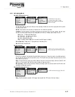
7: Options
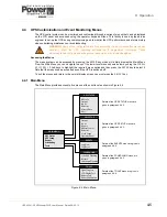
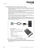
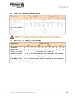
Figure 7.3 Maintenance bypass connector (MINIpowerPLUS 5000)
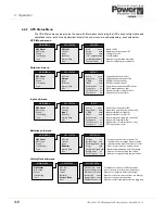
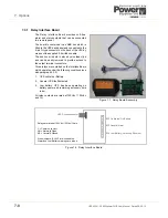
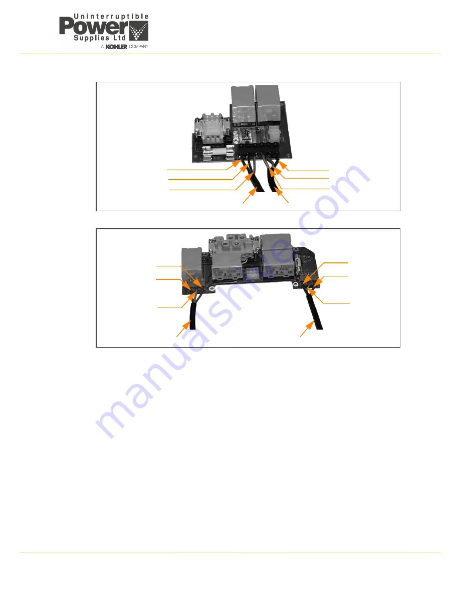
Figure 7.4 Maintenance bypass connector (MINIpowerPLUS 10000)
7.1.3 Functional
testing
1.
Connect the input cable to the mains power supply and connect a load to the UPS output (e.g. a lamp).
2.
Turn ON the UPS input mains power.
3.
With the UPS switched off, verify the following:
a)
With the maintenance bypass switch in position I (MAINS), the yellow lamp illuminates in the switch
and the load receives power.
b)
With the maintenance bypass switch in position 0 (UPS), the yellow lamp in the switch extinguishes
and the load receives no power.
4.
Switch ON the UPS and check that the load receives power when the bypass switch is in both positions.
If this does not occur:
a)
Check the connection of the cables and the supply voltage rating.
b)
Check that the UPS power connector is fully inserted into the UPS power receptacle.
5.
If the above checks prove satisfactory:
a)
Shutdown the UPS and turn OFF the input mains supply.
b)
Disconnect the test load (lamp) and reconnect the normal load equipment.
6.
Start the UPS following the procedure given in Chapter 4.
Live
Neutral
PE
Live
Neutral
PE
Mains input cable
UPS output cable
Live
Neutral
PE
PE
Neutral
Live
UPS output cable
Mains input cable
Summary of Contents for Minipower Plus Rack
Page 1: ...Pioneering solutions for total power protection MINIpower PLUS User Manual ...
Page 2: ......
Page 8: ...1 Safety 1 2 UPS453 01 00 MINIpowerPLUS User Manual Dated 08 03 12 ...
Page 26: ...3 Installation 3 12 UPS453 01 00 MINIpowerPLUS User Manual Dated 08 03 12 ...
Page 40: ...5 Maintenance 5 2 UPS453 01 00 MINIpowerPLUS User Manual Dated 08 03 12 ...
Page 42: ...6 Troubleshooting 6 2 UPS453 01 00 MINIpowerPLUS User Manual Dated 08 03 12 ...


