UPS725-02-02 PowerWave 1000 (4.5 - 10 kVA) User Manual UK Dated 13/03/15
15
2: General Description
2.5.1 Communication options
Several communication options can connected to the PowerWave 1000 rear panel. These are described briefly below with
further details provided in chapter 8 (Options).
RS-232 Interface port (Figure 2.7 item 2)
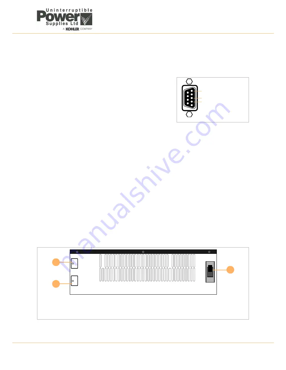
The RS-232 port also allows the UPS to be connected to a PC. It can be used
with the UPS external monitoring and shutdown software (WAVEMON) and
with the supplied UPS Configuration Software.
The RS-232 interface should be set as follows:
Emergency power off (EPO) (Figure 2.7 item 4)
If an external emergency power off (EPO) facility is required, a normally-open circuit must be connected to the two pin
plug located on the UPS enclosure rear panel. When the external emergency power off circuit is operated it connects a
short-circuit across these terminals and effects a total UPS shutdown. A plug-in connector with screwed terminals is
supplied ready fitted to the EPO socket to simplify the connection of the external cable if the UPS is located in a confined
space such as when it is rack mounted.
Optional interface card slot (Figure 2.7 item 6)
Four optional interface cards are available to meet various communication needs: DCE (dry contact relay card), R2E, USE
and SNMP/Web. These cards can be fitted into the options slot located behind a blanking plate on the UPS back panel, as
shown. Full installation and set-up procedures are provided in chapter 8.
The software bundled with the UPS is compatible with most operating systems including Windows 98, 2000, ME, NT and
XT. For other applications, such as Novell Netware, Unix or Linux please contact your local dealer for suitable products.
All of the fitted communication ports, including the optional cards, can be active and used simultaneously to monitor the
UPS status. However, only one communication (the one with the highest priority) has the ability to command and control
the UPS at any given time.
The priority of the communication interfaces are:
1. EPO input port.
2. Optional slot-mounted interface card.
3. RS-232.
2.6
Battery enclosure rear panel
Figure 2.9 Battery enclosure rear panel detail
Baud Rate
2400 bps
Data Length
8 bits
Stop bit
1 bit
Parity
None
Pin 5: Ground
Pin 3: RS232 Rx
Pin 2: RS232 Tx
Figure 2.8 RS232
To UPSBattery
DC Breaker
30A 250Vdc
To ExtendedBattery
1
3
2
1
Battery cable connection from UPS enclosure.
2
Battery circuit breaker.
3
Battery cable connection to Extended Battery enclosure (option).


