UPS725-02-02 PowerWave 1000 (4.5 - 10 kVA) User Manual UK Dated 13/03/15
21
3: Installation and Set-up
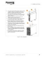
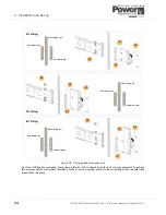
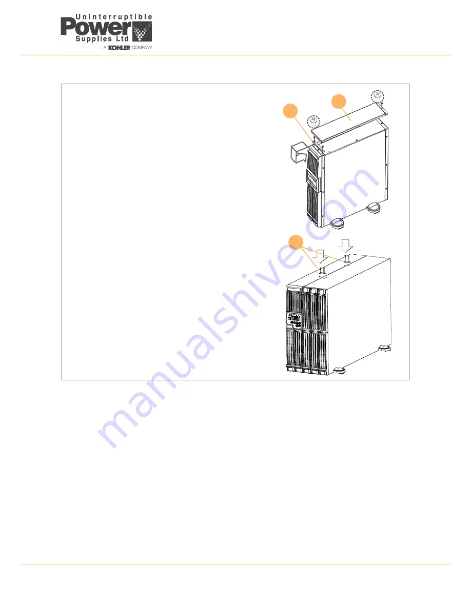
Figure 3.4 Tower configuration
A3
A2
A3
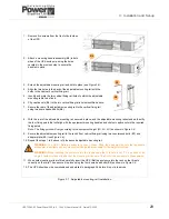
6. If necessary, rotate the UPS control panel so that it is correctly
orientated. To achieve this, carefully pull the control panel
forward to unclip it from its mounting, rotate it to the correct
angle, then relocate it and press it back into place.
7. Remove three screws from the top of the each enclosure (two
from the front and one from the back), as identified in the top
diagram of Figure 3.4.
8. Remove two screws from the top of each enclosure as
identified in the bottom diagram of Figure 3.4.
9. Fit two tie bars (A3) between the enclosures, using screws S1,
to secure them together (Figure 3.4 bottom diagram).
10. Attach the angle brackets (A2) to the top front of the UPS
enclosure, using two screws, such that the lip of the bracket
faces the front of the enclosure. (Figure 3.4 top diagram).
11. Locate the new UPS enclosure top panel (A3) into the bracket
(A2) and secure it in place by screwing it to the top rear of the
enclosure using a single screw.
12. Repeat the above two steps to fit the new top cover to the
battery enclosure.
13. Move the completed UPS tower assembly to its final location
then connect the battery cable between the UPS and battery
enclosures. The battery cable must be secured in place using
the clamp (attached).
14. This completes the tower hardware configuration. The UPS
should now be commissioned as detailed in paragraph 3.6
before it is put into service.


