UPS725-02-02 PowerWave 1000 (4.5 - 10 kVA) User Manual UK Dated 13/03/15
27
3: Installation and Set-up
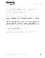
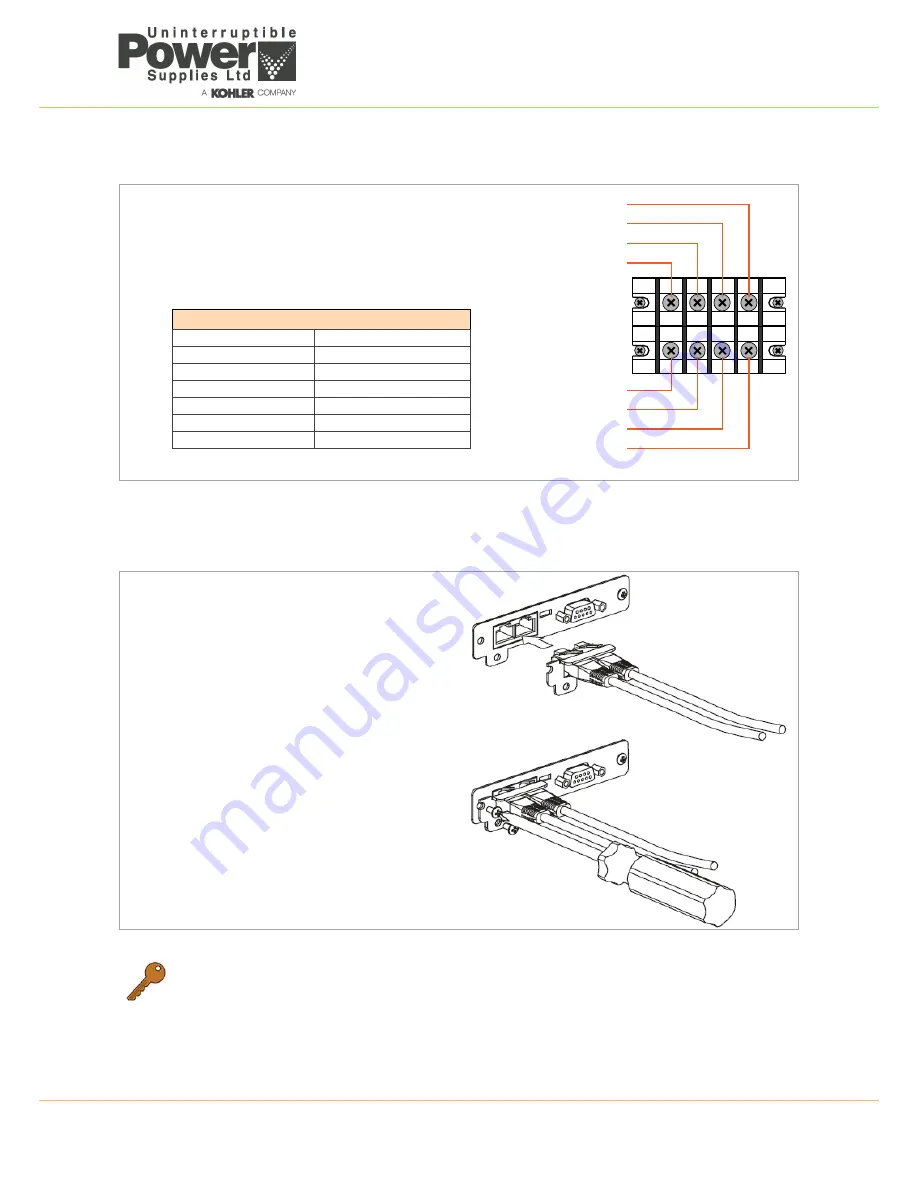
10.0 kVA (three phase input) UPS
Figure 3.11 10 Kva (three phase input version) power connections
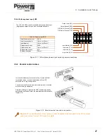
3.5.2 Parallel control cables
Figure 3.12 Parallel control bus cable connection
Key Point:
For a parallel system it is necessary to utilise a bespoke distribution panel for the UPS input and
output connections. Contact UPS Limited for details.
Output Live [L21]
Output Neutral [N22]
O/P Earth (Ground) [G2]
Input Line [S] L2
Input Line [T] L3
Input Line [R] L1
O/P Earth (Ground) [G1]
The 10.0 kVA UPS model is available as a three-phase input
(single phase output) version, and connected as shown.
Input Neutral [N1]
10 kVA 3 Phase input UPS
Input lines max current
54.3 A
Input lines conductor
16 mm² or 25 mm²
Input Neutral
16 mm² or 25 mm²
Output max current
54.3A
Output conductor
16 mm² or 25 mm²
Battery max current
41A
Battery conductor
10 mm²
In a parallel module system a control bus, formed by RJ45
terminated cables, is connected between all the UPS
enclosures in a ‘ring’ configuration.
The cables are held in-situ by a metal clamp which is secured
by two screws, as illustrated.
Note that, although in practice the UPS modules are usually
positioned close to each other, the maximum parallel bus cable
length is 7m.


