4: Single Module Operating Procedures
38
UPS725-02-02 PowerWave 1000 (4.5 - 10 kVA) User Manual UK Dated 13/03/15
4.1
Single module start-up procedures
4.1.1 Normal start-up (utility available)
1. Turn
ON
the UPS utility input supply (and bypass supply if separate) then
close the input circuit breaker(s) and battery circuit breaker located on the
back of the enclosures.
a) The UPS fans will start.
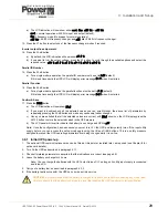
b) The UPS control system will boot-up and initially turn on all the leds and
LCD symbols for a few seconds.
c) Once the control system has booted, the
ECO*
,
N+1
and
FAULT
leds will
extinguish, leaving only the utility input and bypass input power leds
(green) illuminated.
d) The LCD mimic will show the ‘load on bypass’, the battery being
charged, and the UPS output status will be shown as
off
.
2. Press and hold the UPS
ON
button for approximately 3~5 seconds until you
hear two beeps, then release it.
a) The UPS will indicate the bypass voltage.
b) The audible alarm will sound intermittently but can be silenced by
pressing the alarm silence (
ON
) button.
3. The UPS will run another self
test
for about 4 seconds to check the battery
operation.
a) If the UPS does not complete its self test successfully the LCD will show
a
FAIL
status and the
FAULT
led will illuminate.
b) If the self test is successful the LCD will show an OK status for about 5
seconds then change over to display the normal on-line indications
**
.
c) The utility input and bypass input power leds (green) remain illuminated.
4. You can now check all the metered input, output and battery parameters to
ascertain that the UPS is working correctly (see page 40).
* If the machine is set to operate in the ECO mode the ECO led will be
illuminated throughout this procedure.
** If the machine is set to operate in the ECO mode the ECO the screen will
continue to indicate the on-bypass mode.
4
Single Module Operating
Procedures
CAUTION: When turning on the UPS for the first time, or following a long shut down period, leave the unit
running for at least eight hours to fully charge the batteries before connecting any critical load, otherwise you
may not obtain the specified battery autonomy time if the utility input supply fails.
LINE
UPS
LOAD
V
1
2
EC
O
N+
1
LINE
UPS
LOAD
V
A
%
Hz
C
LOW
?
1
2
EC
O
N+
1
LINE
UPS
LOAD
1
2
EC
O
N+
1
LINE
UPS
LOAD
V
1
2
EC
O
N+
1
LINE
UPS
LOAD
1
2
EC
O
N+
1
LINE
UPS
LOAD
1
2
EC
O
N+
1

