UPS469-01-00 PowerWAVE 3000T User Manual Dated 05-04-13
3-3
3: Installation
3.2
Planning the installation
A certain amount of pre-planning will help ensure smooth, trouble-free installation. The following
guidelines
should be considered when planning a suitable UPS location and environment.
Moving the UPS to is final location
1.
The floor material where the UPS is to be located should be non-flammable and capable of safely
supporting the weight of the UPS module and battery equipment.
2.
The floor on the route between the off-loading point and the proposed installation location must be able
to safely take the weight of the UPS and battery equipment plus any transit handling equipment.
3.
The route between the off-loading point and the installation location must be suitable to allow the
equipment to be transported in an upright position.
Environmental considerations
1.
The UPS location should be subject to a humidity of less than 90% (non-condensing) and temperature
b15°C to +25°C. An ambient temperature of 20°C is recommended for optimum battery life.
2.
The location should be free from dust or corrosive/explosive gases.
3.
The location should not be subject to vibration.
4.
The UPS cabinet requires space to the bottom, front and back to permit unrestricted cooling air flow. The
air conditioning system must be able to provide a sufficient amount of cooling air to keep the room at, or
below, the maximum permissible operating temperature.
Equipment accessibility
1.
The available cable routing must be planned to enable the cables to be easily accessed when connecting
the UPS (and optional battery cabinet where used) – also see
cable preparation and planning
in the
paragraphs below.
2.
A space of 200mm is required at the rear of the UPS for ventilation, however cabinets ‘A’ and ‘B’ should
be cabled such the cabinet can be pulled forward to give service access.
3.
A space of 600mm is required at both sides of the UPS cabinet to facilitate service and maintenance. A
space of 900mm should be provided at the front of the cabinet to allow easy passage with the cabinet
door open
(See Figure 3.1)
.
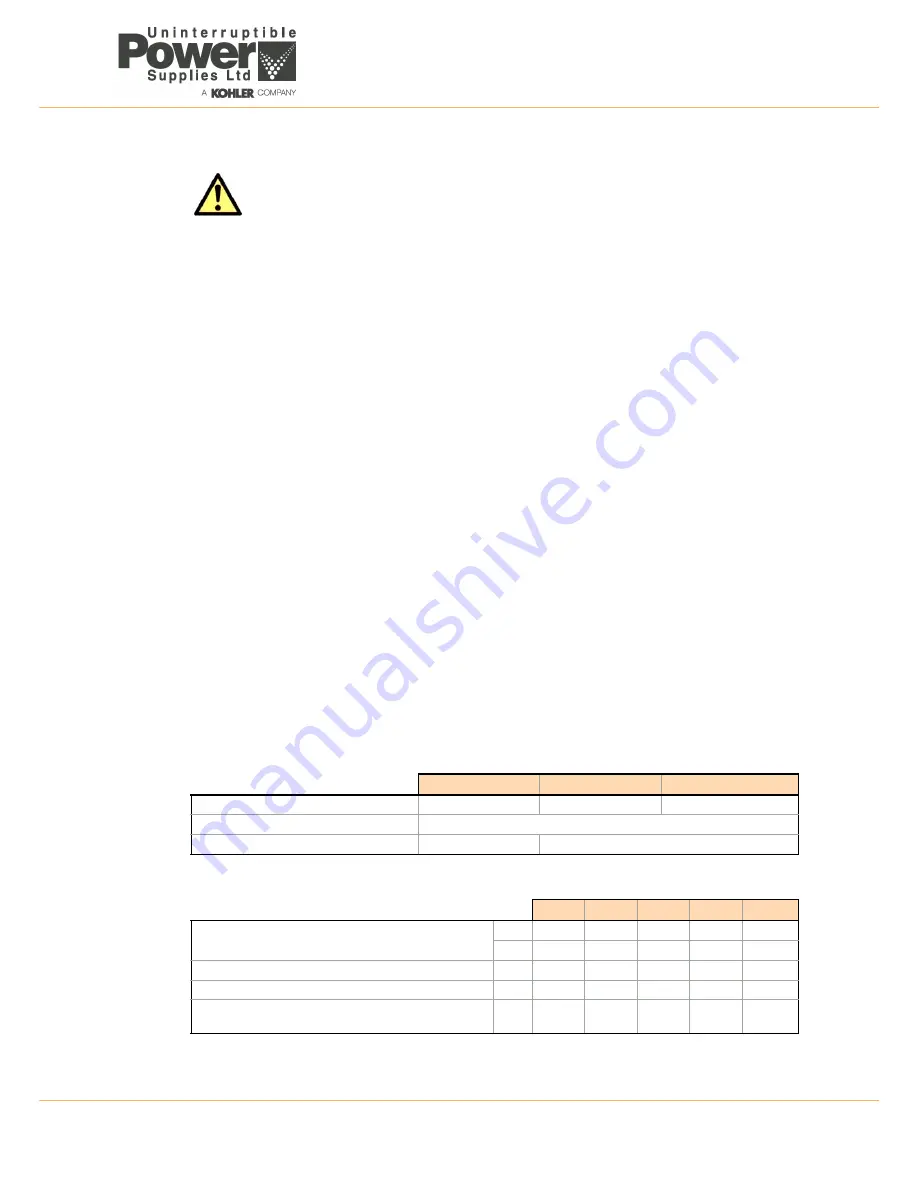
Cabinet Dimensions
Heat Dissipation
CAUTION: Sealed batteries must never be stored in a discharged or partially discharged state.
Extreme temperature, under-charge, overcharge or over-discharge will destroy the batteries!
Cabinet A
Cabinet B
Cabinet C
Dimensions (WxDxH) mm
340x800x820
450x860x1250
550x890x1650
Accessibility for service and maintenance.
Front + left and right sides
Input and Output Power Cabling
From the bottom rear
From the bottom front
7.5kVA
10kVA
12kVA
15kVA
20kVA
Heat Dissipation with 100% Non-linear Load (EN 62040-3)
W
460
600
650
800
1120
BTU/h
1638
2048
2218
2730
3822
Heat Dissipation with 100% Load (pf=0.8)
W
380
500
550
700
800
Heat Dissipation with 100% Load (pf = 1.0)
W
400
550
600
750
960
Airflow (25°C - 30°C) with 100% Non-linear Load per range
(EN 62040-3)
m³/h
110
110
110
150
200
Summary of Contents for PowerWave 3000T
Page 1: ...Pioneering solutions for total power protection PowerWave PW 3000 T User Manual ...
Page 2: ......
Page 8: ...1 Safety 1 2 UPS469 01 00 PowerWAVE 3000T User Manual Dated 05 04 13 ...
Page 30: ...3 Installation 3 18 UPS469 01 00 PowerWAVE 3000T User Manual Dated 05 04 13 ...
Page 44: ...4 Operation 4 14 UPS469 01 00 PowerWAVE 3000T User Manual Dated 05 04 13 ...
Page 56: ...7 Options 7 8 UPS469 01 00 PowerWAVE 3000T User Manual Dated 05 04 13 ...


